Flicker (MMP)
Image Quality FactorsIntroduction
Light flicker is defined as a periodic change to the brightness or intensity of a light source. This change can be intentional, e.g., a flashing light from an emergency vehicle, or unintentional, e.g., light fluctuations from digital road signs. As a result of its changing nature, flicker can be challenging to quantify in a test setting. Nevertheless, with the continuing advancement of cameras and sensors in specific industries, such as advanced driver assistance systems (ADAS), other automotive systems, and security, it is imperative to recreate and test flicker in a lab setting.
Modulate Mitigation Probability (MMP)
In traditional camera testing, camera systems are generally not tested for flickering light performance. Other cameras, such as automotive systems, must perform at the highest level in any illumination scenario to ensure safety standards are met.
The IEEE-P2020* working group has published the first internationally recognized standard for image quality performance of ADAS systems. This group is made up of industry experts from a variety of fields. Many of our dedicated automotive camera testing engineers are active members. One of the KPIs in the standard is modulation mitigation probability (MMP). MMP is the main KPI in the standard for testing the camera system's response to flickering light.
*Disclaimer: The opinions contained within the IEEE-P2020 working group solely represent the views of this working group and do not necessarily represent the position of either the IEEE or the IEEE Standards Association.
How does flicker occur?
Flicker often occurs from LED-based light sources using pulse width modulation (PWM) technology to control light intensity. Flicker is a temporal light modulation (TLM) of the light that hits a camera sensor. As that sensor has a discrete sampling of light intensity (exposure time), the combination of the light turning on and off quickly and the capturing process can lead to unwanted artifacts.
The number of observable artifacts in an image or video due to flickering light sources depends on the frequency and duty cycle of the PWM used in the light source and the phase shift between the light source and the camera's capture rate.
In the automotive industry, flickering light is divided into two categories: reflectance flicker and illuminant flicker.
Reflectance flicker
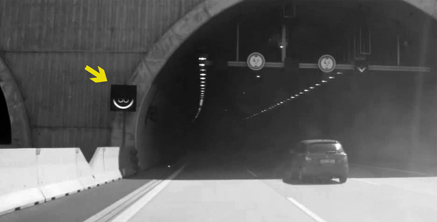
Reflectance flicker refers to a flickering light source that illuminates the scene but is not within the camera's field of view (e.g., illumination in a parking garage). We evaluate reflectance flicker using the flicker modulation index (FMI).
$$FMI=100 \frac{x_{max}-x_{min}}{x_{max}+x_{min}}$$
xmax= The maximum signal measurement of the PWM light source captured by the image sensor for the entire captured video sequence
xmin= The minimum signal measurement of the PWM light source captured by the image sensor for the entire captured video sequence
Illuminant flicker
Illuminant flicker refers to a flickering light source that illuminates the scene within the camera's field of view (e.g., headlights of an approaching vehicle). We evaluate illuminant flicker using the same FMI equation seen above. Illuminant flicker, however, can often cause various HDR artifacts to occur in the scene. Thus, we use the flicker detection index (FDI) to evaluate the likelihood that the captured image will have enough contrast between the LED light and a light reference level for a given camera, duty cycle, etc.
$$FDI=Prob\left(\frac{x_{meas}-x_{ref\text{_}off}}{x_{ref\text{_}off}}\ge \tau \right)$$
Prob= empirical probability / xmeas= measured flickering signal level / xref-off= reference background ("off") light level / τ= flicker contrast threshold
While the FDI equation is a good indicator of flicker detection, it is not as accurate if the system must reproduce the light source signal level, which is typically required for automotive-grade cameras. Therefore, we utilize the modulation mitigation probability equation developed under the direction of the IEEE-P2020 working group. This equation will provide the likelihood that the captured image will accurately reproduce the light source signal level compared to a reference light source.
$$MMP=Prob\left[ \overline{x_{ref\text{_on}}}\left( 1-\delta\right) \lt x_{meas} \lt \overline{x_{ref\text{_on}}}\left( 1+\delta \right)\right]$$
Prob= empirical probability / xmeas= measured flickering signal level / xref-off= reference expected light level / δ= acceptable threshold level
The importance of testing flicker
Light flicker can affect almost all industries that rely on cameras and sensors, but it's most evident in the automotive and security sectors. Flicker is common in these industries because the surrounding environments constantly change, producing a broad range of lighting situations. The camera and sensor systems in these industries need to mitigate the modulation of the light source (flicker) to adapt to the changing environment and ensure high performance and safety. For example, an ADAS system must always react correctly to avoid a dangerous driving situation, even with an inconsistent light flicker.
Industry engineers understand the importance of flicker but find it difficult to reliably test different flicker situations in the test lab. As a result, our engineers at Image Engineering have developed various hardware and software solutions that can accurately reproduce light flicker in a test lab setting and then evaluate the camera's response to the flickering conditions.
Flicker test methods
Flicker has proven to be one of the more challenging camera system KPIs to recreate in a test lab setting. Cameras with short exposure times often experience stability problems due to inadequate testing devices. At IE, we have designed various illumination devices that can accurately simulate flickering scenarios for more reliable test results. Remember that a proper device must allow you to control the light source's intensity, frequency, duty cycle, and phase.
Once you have reliable test equipment, the next step is properly setting up your test scene. When testing reflectance flicker, we recommend setting up the light sources right outside the field of view of the device under test (DUT). For illuminant flicker, the light sources should be within the direct field of view of the DUT.
Tools for testing flicker
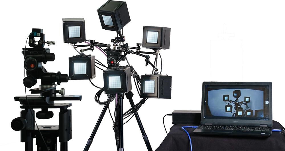
Vega - a DC-powered light source
The Vega light source is a powerful solution for high-precision measurements of the exceedingly short exposure times often seen in automotive-grade cameras. Vega uses thermally stabilized LEDs driven by DC (direct current) technology, which makes it one of our most sophisticated and unique light sources.
Vega has exceptionally high stability, providing a previously unattainable consistency for measuring these cameras with very short exposure times. We actively stabilize the temperature so that the DC driver does not affect temperature regulation, and we can achieve temperature stability within half a degree. The temperature system works both ways (i.e., heating and cooling) and will remain consistent even when turning on/off the light output or changing the intensities.
Vega generates flicker from a wide frequency range. We have further developed the low-frequency functionality to include sine, triangular, and square waveforms, covering nearly all real-world scenarios. Vega utilizes uniquely designed grayscale test charts optimized for system evaluations with very short exposure times.
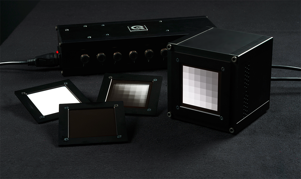
Testing flicker with the LG3
The LG3 illumination box is the first lightbox on the market with flicker capabilities. Based on LED technology, the LG3 greatly expands the test areas for dynamic range measurements with the ability to illuminate a high-contrast test target with over 150,000 lx. It is used with transparent test charts such as the TE269 test chart.
The TE269 test chart follows not only ISO 14524 and ISO 15739 but also IEC 62676-5, the first international standard regarding the measurement methods and descriptions of security and surveillance cameras. The chart is suited for high dynamic range measurements of 1,000,000:1 / 120 dB.
The flicker mode ranges from 10 to 500 Hz and has a variable duty cycle, which can simulate varying flicker frequencies, e.g., traffic and streetlights. There is also a 32 kHz/128 kHz mode and a variable duty cycle.

Conclusion
Flicker has proven to be one of the more challenging camera system KPIs to recreate in a test lab setting. Cameras with short exposure times often experience stability problems due to inadequate testing devices. At IE, we have designed various illumination devices that can accurately simulate flickering scenarios for more reliable test results. Remember that a proper device must allow you to control the light source's intensity, frequency, duty cycle, and phase; we recommend Vega and VLS.
Once you have reliable test equipment, the next step is properly setting up your test scene. When testing reflectance flicker, we recommend setting up the light sources right outside the field of view of the device under test (DUT). For illuminant flicker, the light sources should be within the direct field of view of the DUT.