Flare
Image Quality FactorsIntroduction
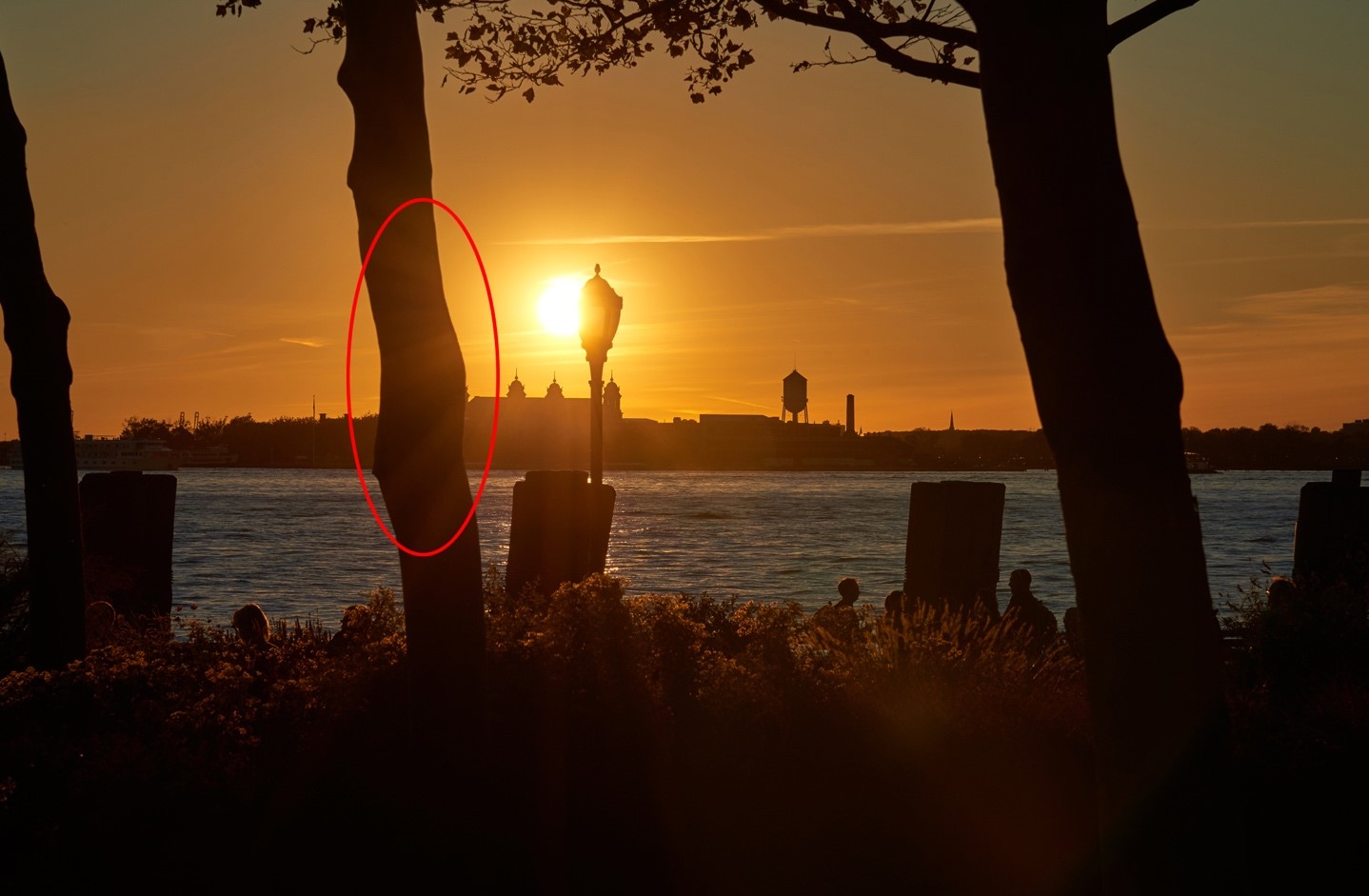
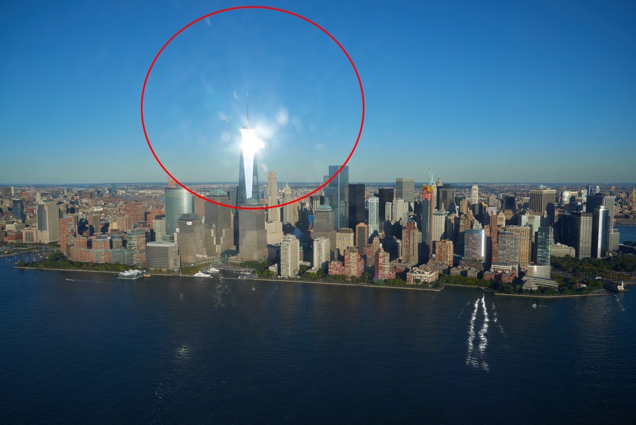
Flare (also known as glare or veiling flare/glare) by definition is unwanted light in an image that did not originate from the related scene object. Flare can occur from multiple sources and, when present, can significantly disrupt the quality of an image.
Veiling flare vs. image flare
Both veiling flare and image flare can hurt the final image. For example, veiling flare, according to ISO 93581, describes flare from a traditional camera lens. It is measured for just the lens removed from the camera. ISO 9358 outlines the test methods and procedures for analyzing veiling flare.
Image flare, meanwhile, describes the flare that occurs in the final processed image of a camera such as a mobile device. In many cases, detaching the camera lens is not possible. It is unknown if a certain amount of flare originates from the lens, the camera, or even the camera's image processing. As a result, ISO 188442 was created to outline a systematic approach to evaluating image flare for all types of cameras.
How does flare occur?
Flare can occur from many different variables, including those from natural causes and those from the camera system's hardware components.
Sources for flare include:
- Everything between the object and the camera's front lens, e.g., haze or dust in the air.
- Interreflections between the optical parts of the lens and dust and dirt on the lens elements.
- Light reflected from the edges and framing of the lens or the shutter, diaphragm, camera body, etc.
- Light from the optical system itself with spherical aberration and chromatic aberrations etc.
- Light leakage
Such an expansive range of variables, flare is often one of the more difficult image quality factors to measure.
How to measure veiling flare?
ISO 9358 is the basic standard for measuring the flare of lenses. There are four different ways to measure veiling flare using ISO 9358, and they are:
- Point spread function
- Using an integrating sphere for infinite measurements
- Using two integrating spheres for lenses with a considerable focal length
- Chart based measurements for non-infinite measurements
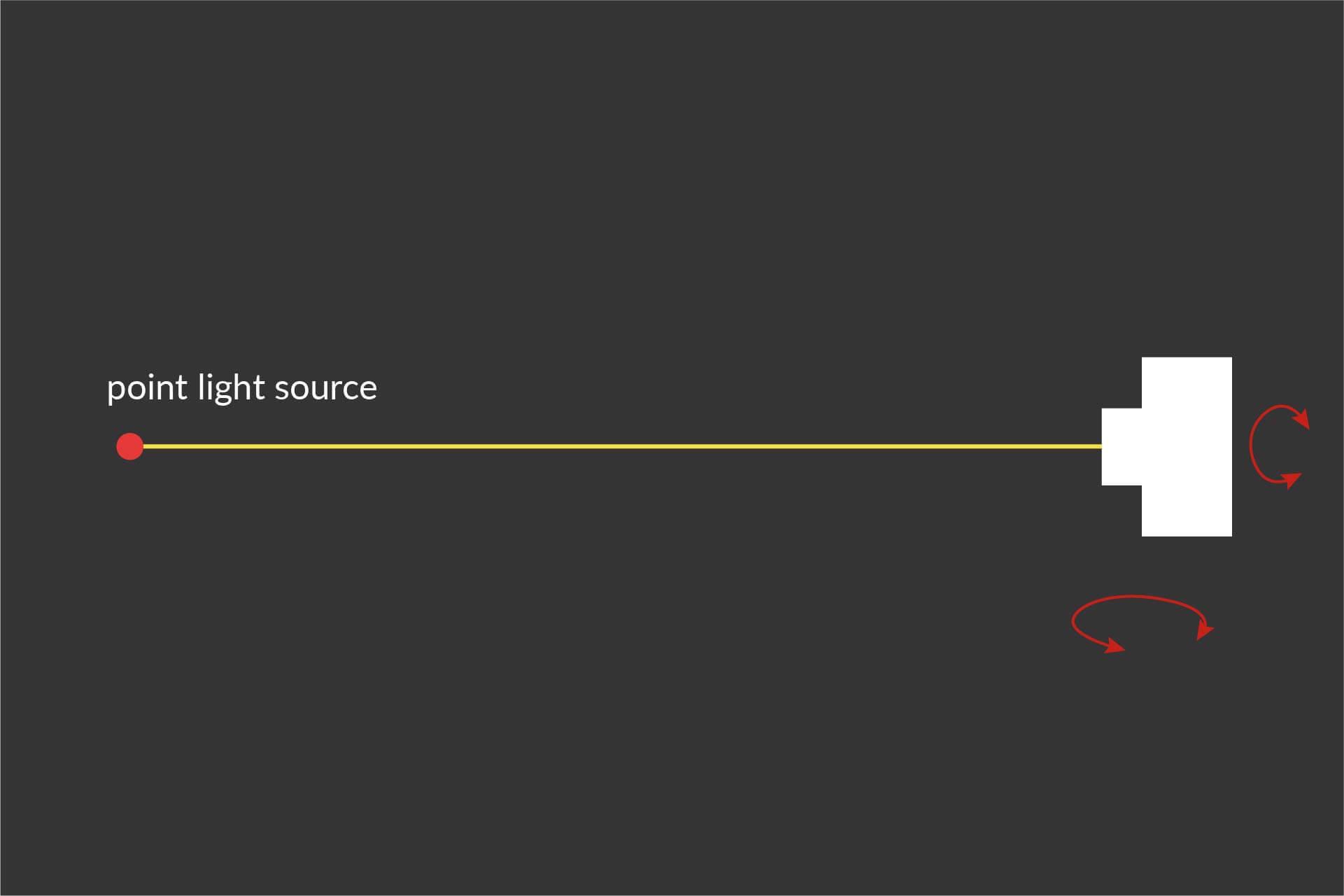
Point spread function
The point spread function is measured by shining a small point light source onto the camera. The camera is then repeatedly rotated so that the light shines on the camera from all different angles. The resulting images are evaluated for flare, but there is currently no method to get a single number indicating the amount of flare present in these images using this measurement method.
Using an integrating sphere for infinite measurements
The second method mentioned in ISO 9358 uses a light trap in an integrating sphere. The black level measured in the light trap area is an indication of the amount of flare present. Two integrating spheres should be combined if there is a large focal length. ISO 9358 defines the infinite distance as a distance larger than ten times the focal length. Therefore, the integrating sphere's diameter (the distance between the lens and the light trap) needs to be at least ten times the focal length.
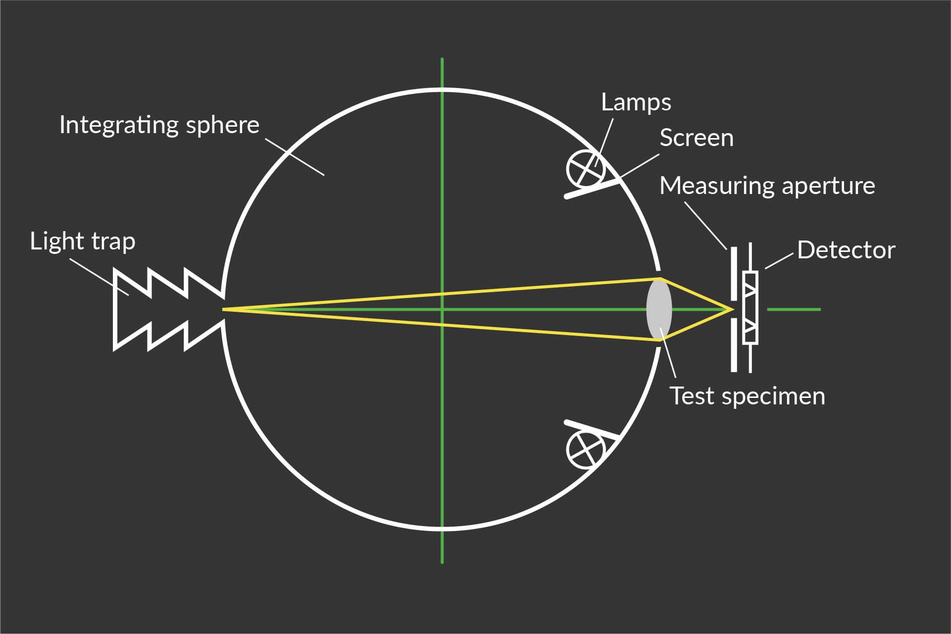
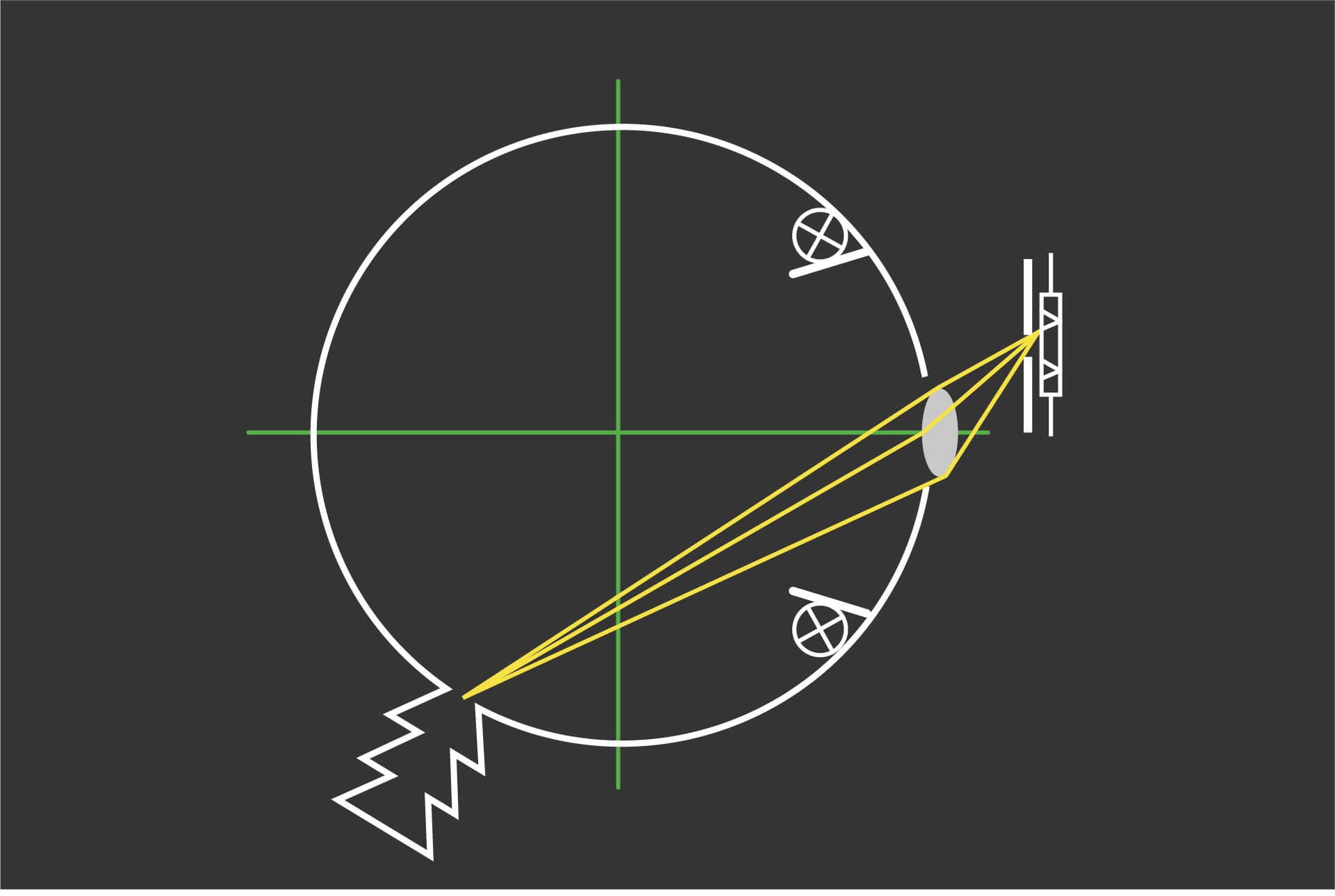
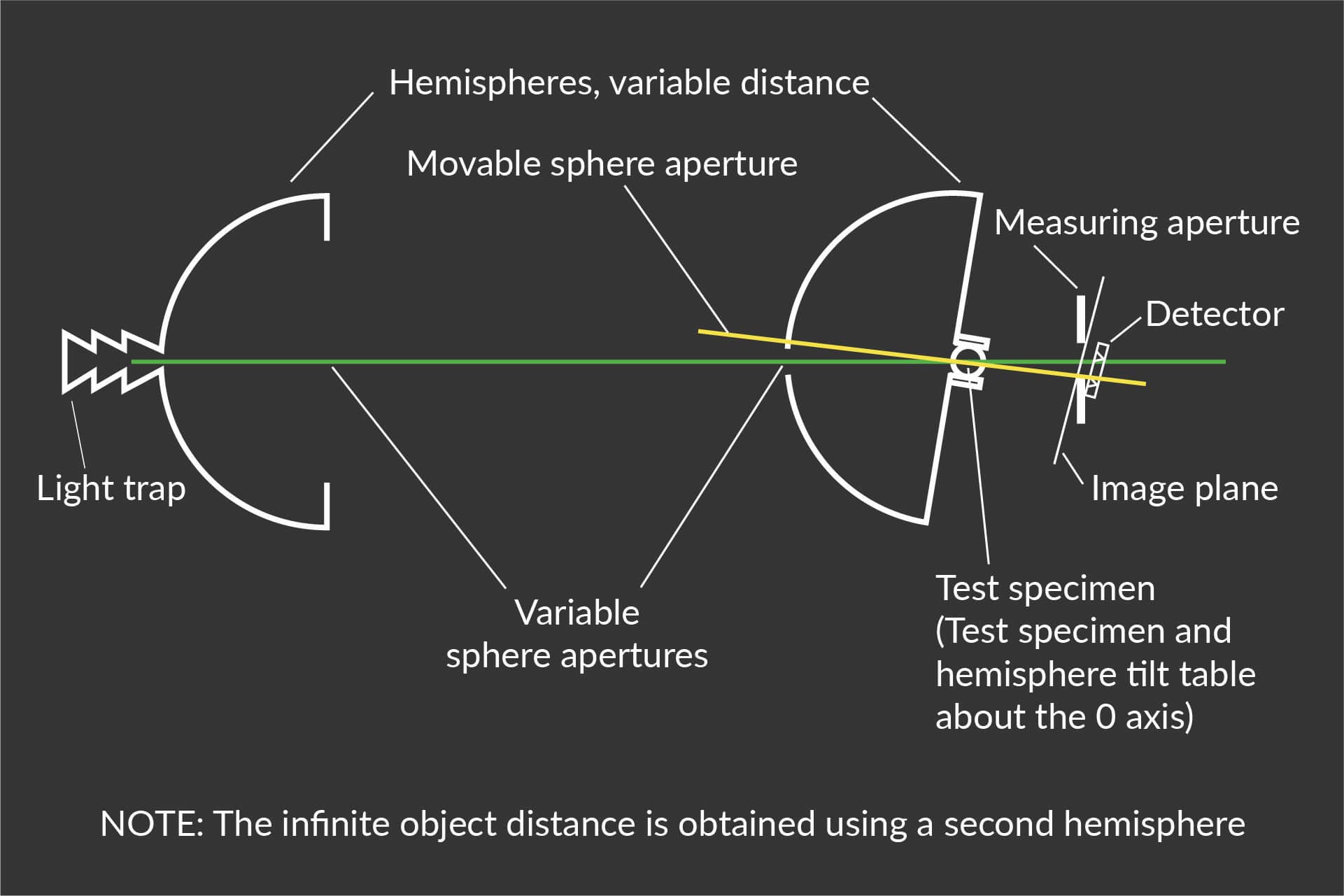
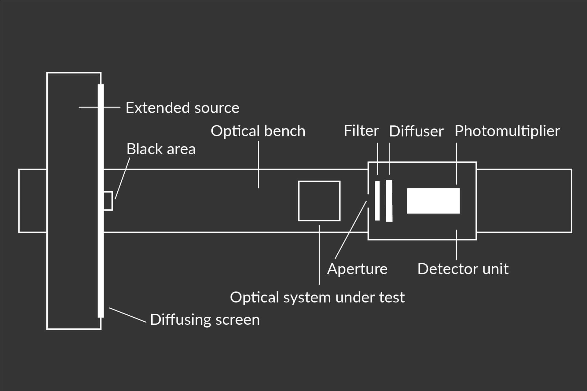
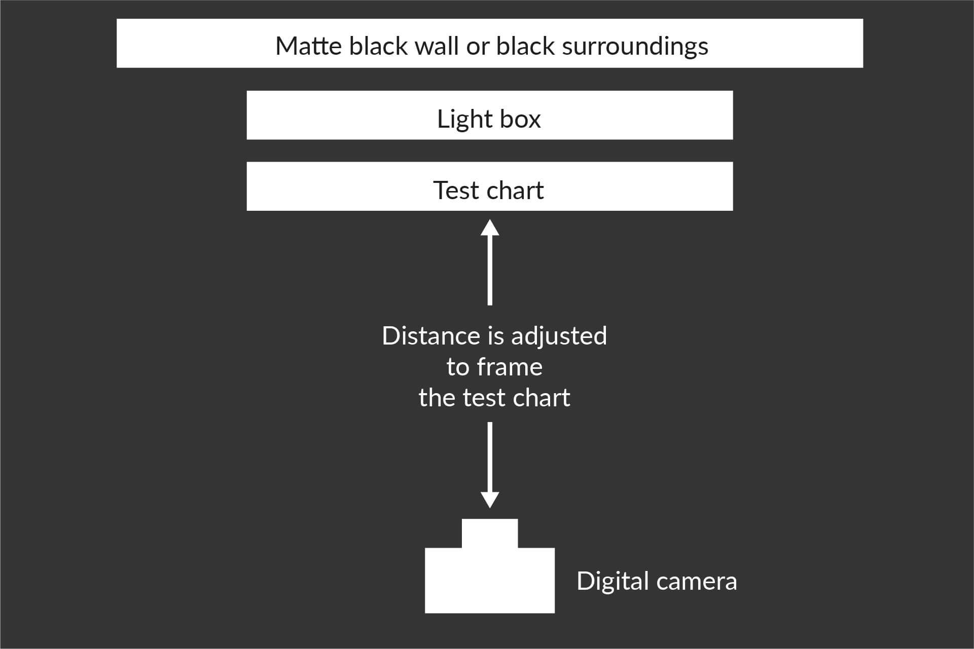
Chart based method for non-infinite measurements
A test chart can be used if the flare does not need to be measured at infinite distances. ISO 9358 uses a transparent test chart in its test setup, as seen in figure 4.
How to measure image flare using ISO 18844?
ISO 18844 is the best standard to use when analyzing a mobile phone's flare (or similar) camera system. Unlike ISO 9358, which has multiple methods for measuring flare, ISO 18844 measures image flare using specifically designed test charts similar to the charts from the non-infinite method of ISO 9358.
These test charts are uniform white targets with at least one black hole for determining the amount of flare added to the image by the camera. The black hole acts as a light trap that absorbs a high proportion of the light, thereby creating the lowest possible level of black. This level of black will rise if there is flare present in the image. This test chart can be either reflective or transmissive.
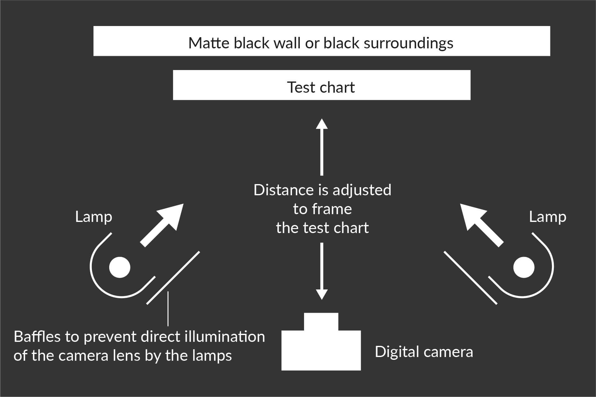
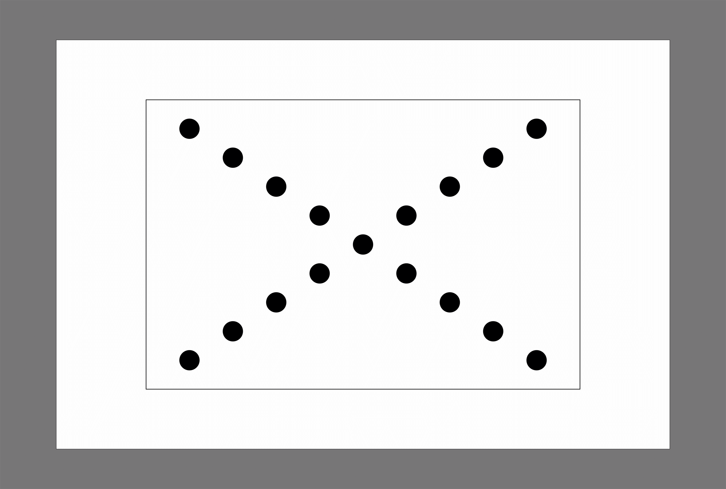
The chart shown below is designed specifically around the description given in ISO 18844. It uses 17 light traps to capture the maximum light possible while also providing multiple analysis points. The contrast reaching more than 10.000:1 is sufficient when using the simplified method C as described in ISO 18844. From a single image, we can obtain the ratio between the black and white levels to indicate the flare amount.
As described in ISO 18844, this method currently does not consider other light and light sources that are located outside the camera's field of view, even when these light sources are often relevant to flare.
At this time, the responsible ISO group and Image Engineering are looking into various options to solve this problem.
Conclusion
Flare can be adequately analyzed using the methods described in either ISO 9358 or 18844. ISO 18844, however, targets all camera system types, including those without the possibility to detach the lens (a requirement for ISO 9358).
When analyzing flare in our test lab, we almost always follow ISO 18844 because it's the most recent version and encompasses many camera systems, including, most importantly, mobile phone cameras.
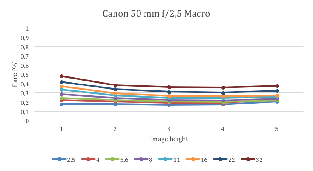
Using a test chart designed for flare (as described above) combined with proper illumination has consistently proven to provide the best results when analyzing where you can improve a camera system for flare.