Introduction
Machine vision camera systems are more prevalent than ever in today's world as we rely more on automation and robotics to increase efficiency, safety, and performance. These systems enable machines to perceive and analyze their surroundings to complete tasks using sophisticated cameras, sensors, and processing systems to detect and interpret objects within a field of view.
Machine vision systems are critical to numerous applications, including manufacturing, robotics, logistics, automated driving, and virtual reality. Because they are vital to our advancing society, these machine vision systems must be thoroughly tested during development to ensure high performance and safety.
What do machine vision cameras do?
Essentially, they capture and process visual data to perform specific tasks. Unlike traditional camera systems (e.g., DSLR or mobile phone cameras), prioritizing image quality desirable to a human observer, machine vision systems are tailored to tasks requiring high accuracy. Thus, their design emphasizes image quality attributes such as signal-to-noise ratio, high dynamic range, and geometric distortion, enabling them to make accurate decisions even in challenging environments.
Machine vision use case - ADAS
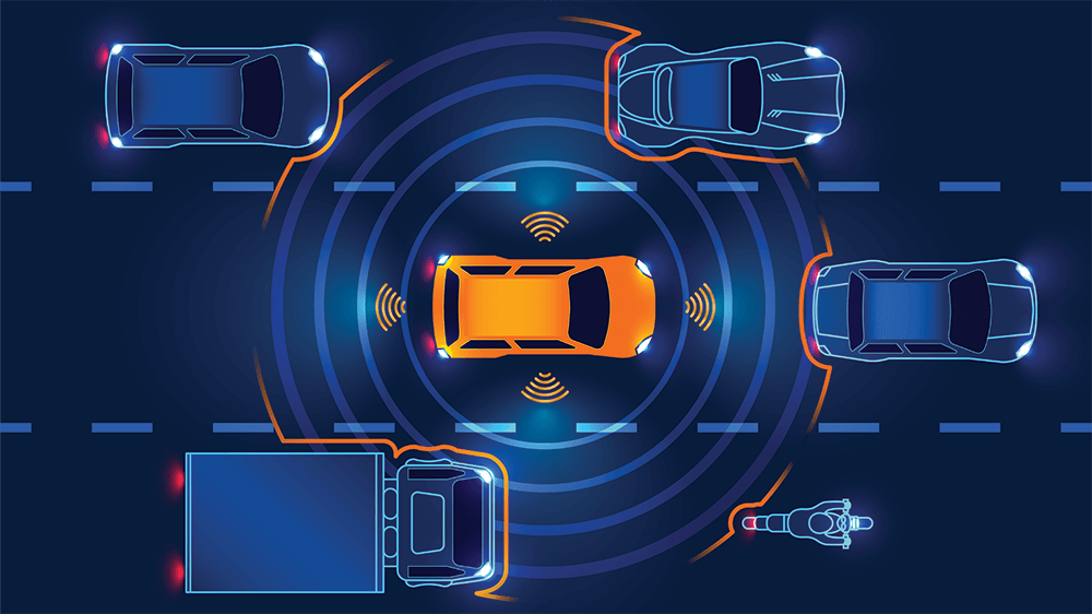
A typical use case of machine vision camera systems functioning in challenging environments is those in vehicle ADAS (advanced driver assistance systems). These systems must accurately detect objects and distances in multiple environments, from direct sunlight to dense fog, and make precise and safe adjustments when necessary. This particular use case deals with life and death and, as a result, must be rigorously tested during development to ensure the highest level of image quality, performance, and safety.
Why image quality performance matters in machine vision
Unlike consumer photography, where subjective preferences help determine image quality performance, machine vision image quality is tied directly to the accuracy of tasks like object detection, classification, or measurement. Poor image quality in machine vision can lead to false positives, missed detections, and inefficient workflows (often with catastrophic results mentioned above in the ADAS use case scenario). Therefore, image quality performance testing is critical to guarantee reliability in real-world operating environments.
Image quality testing ensures the camera is calibrated and optimized under various conditions, including lighting, motion artifacts, and color changes, to achieve high performance. Multiple factors are vital, and all must be tested during development.

EMVA 1288 and ISO 24942
EMVA (European Machine Vision Association) has established and maintained the EMVA 1288 international standard for years. This standard defines crucial KPIs and test methods for evaluating the performance of machine vision camera systems. A few of our engineers, including CTO Uwe Artmann, have actively contributed to developing and maintaining the standard over the years.
In 2024, our CEO, Dietmar Wueller, was nominated to lead the ISO/TC 42/WG 28 to adapt the EMVA 1288 standard to an ISO (24942) standard.
Key Image Quality Factors outlined in EMVA 1288
The following factors are vital when assessing the image quality of machine vision cameras, according to EMVA 1288.
Sensitivity
Camera sensitivity describes how sensitive a system is when it interacts with a particular light level. Understanding how a camera reacts to different light levels is crucial for its overall quality, especially for cameras making safety adjustments based on their scene interpretations.
Noise
Temporal noise refers to the same pixel value fluctuating between various images. This fluctuation is usually random and results from variations in generating a digital value from a single pixel. Noise can impact a machine vision system’s ability to detect and identify small objects and obscure the signal. The worse the signal-to-noise ratio, the more noise we have in the image, and the more the image signal is influenced by noise.
Linearity
Linearity describes the light signals the camera sensor receives in relation to the signal's output. This relationship is vital when attempting to reproduce the scene correctly. Machine vision cameras typically receive numerous light signals and must be able to produce the correct output.
Dark Current
Dark current refers to a small electric current that appears within the image sensor of a camera system. These dark currents are often one of the primary noise sources in the output signal. Machine vision systems are performing at the highest levels, and they must account for these dark currents and adjust for noise.
Spatial nonuniformity
Spatial nonuniformity describes a deviation from pixel to pixel due to dark signals or sensor sensitivity. Understanding these nonuniformities will provide an overview of the spatial variances and allow you to detect a defective pixel or groups of pixels. Defective pixels can alter signals that machine vision cameras use to make adjustments.
Test Methods according to EMVA 1288
The EMVA 1288 standard outlines characterization methods for analyzing the factors listed above. All of these methods require advanced testing equipment for the best results. The solution that we utilize in our iQ-Lab is the AEON Camera Calibrator.
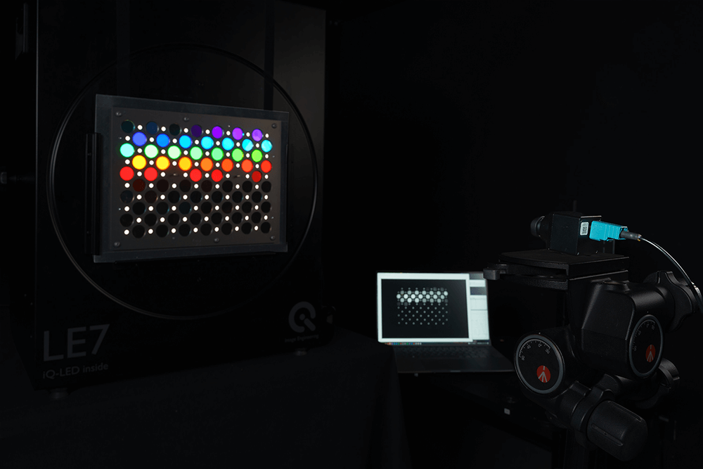
AEON Camera Calibrator (ACC)
We recently partnered with AEON to distribute and market their Camera Calibrator. The ACC is a modular optical system designed to test machine vision cameras based directly on the measurement parameters outlined in the EMVA (European Machine Vision Association)1288 standard.
Parameters include linearity, noise, sensitivity, spatial nonuniformities, and dark current. These measurements can derive results, including absolute gain factor K, sensitivity threshold and saturation capacity, maximal signal-to-noise ratio, dark noise, dynamic range, and nonlinearity.
The ACC is available in two sizes, one designed for standard sensors and another capable of handling sensors with diagonals up to 80 mm. Both configurations are modular, turnkey systems featuring adjustable LED light sources and comprehensive evaluation software.
Other factors to consider
In addition to the KPIs outlined in EMVA 1288, there are many other image quality factors to consider when performing machine vision measurements. An automotive system, for example, must adjust for distortion disruptions. Below is a look at these other crucial factors.
Resolution
Image resolution is a camera's ability to reproduce a scene's details or how many pixels it can detect in the scene. Higher resolution provides greater detail and improves accuracy in detecting minor defects or features in the scene. Resolution is crucial for machine vision cameras that rely on object detection and separation. Without high resolution, cameras may mistake objects or miss them entirely.
We recommend following ISO 12233 and using Siemens stars or slanted edge targets for accurate resolution measurements. TE296 is the latest slanted edge test chart based on the ISO standard.
Dynamic range
Dynamic range refers to the camera's ability to capture contrast and details in the scene's bright and dark areas. Understanding the low-light and bright-light thresholds at which a machine vision system can still detect objects and details at an acceptable level is crucial for making necessary adjustments.
OECF and other grayscale test targets outlined in ISO 14524 are recommended for precise dynamic range measurements. We usually use TE297 and TE269.
Signal-to-noise ratio (SNR)
The signal-to-noise ratio measures the amount of signal or meaningful information relative to the scene's unwanted or disturbing artifacts (noise). Machine vision systems can often detect and differentiate objects even with a higher noise level than would be acceptable for traditional camera systems. However, this noise threshold must be tested under various lighting conditions to determine how much noise is sufficient for the system to function correctly.
Grayscale test targets outlined in ISO 15739 are recommended for noise measurements. These targets can typically be used for dynamic range and noise, including TE269 and TE270X.
Color accuracy
Color accuracy refers to the camera's ability to perceive and reproduce colors correctly. Traditional cameras must be able to generate colors that match the human eye. Machine vision cameras don't have to be so exact; however, especially in the case of ADAS, accurately detecting and processing colors is crucial to the functionality of these systems to make real-world assessments and adjustments.
We recommend color checker test charts for basic color accuracy measurements. We offer basic ColorChecker test charts such as TE188 and TE230.
Distortion
Image distortion occurs when the straight lines of an image appear to be deformed or curved unnaturally. There are three types of lens distortion: barrel, pincushion, and waveform (also known as mustache) distortion. Distortion can lead to geometric inaccuracies and make distances and object sizes difficult for machine vision cameras to gauge.
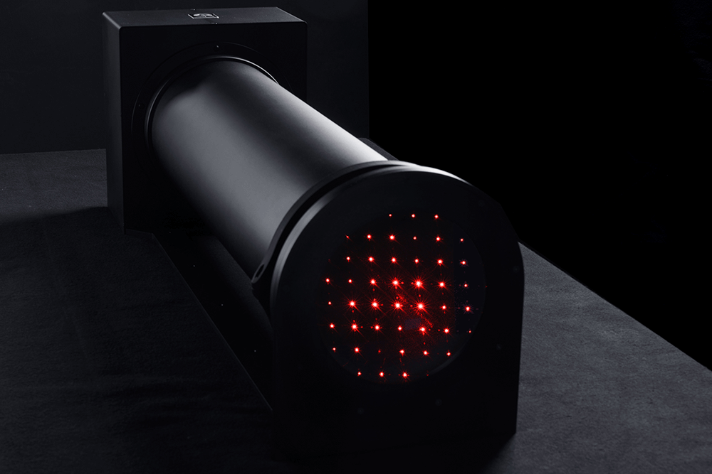
Distortion can be measured using use checkerboard test charts (TE251). However, we have also introduced the GEOCAL, which uses a beam-expanded laser in combination with a diffractive optical element (DOE) to generate a grid of light spots originating from infinity to evaluate distortion performance (more information below).
Shading
Shading refers to a decrease in the image brightness from the center to the corners. When light falls off at the corner of the image scene, a machine vision system may not see particular objects or incorrectly identify a color at the edge of the scene, leading to false interpretations of the environment.
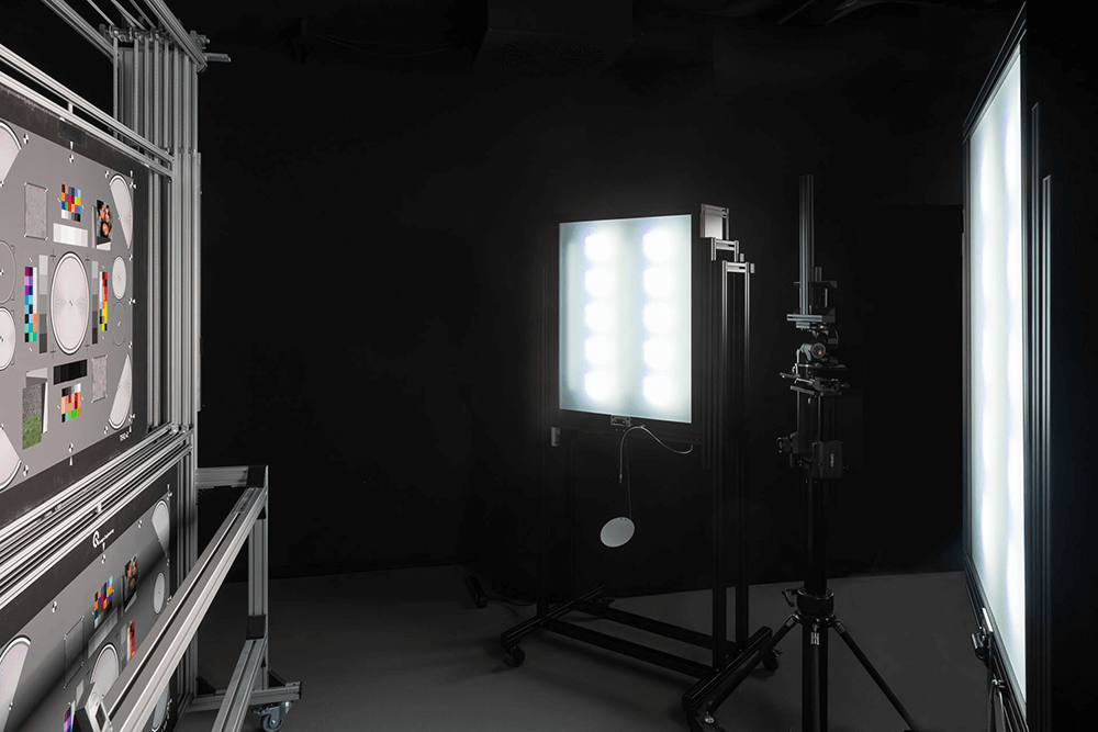
We typically recommend flat-field test charts for testing shading performance. The test chart we use is the TE255 diffuser plate in combination with a LE7 uniform lightbox.
Advanced machine vision testing equipment
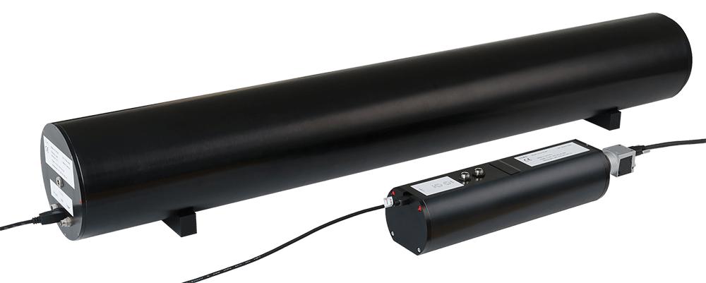
GEOCAL
As mentioned previously, the GEOCAL device offers an advanced geometric calibration option. This device uses a beam-expanded laser in combination with a laser diode to generate a grid of light spots originating from infinity. Instead of using rely lenses and multiple test charts that require large amounts of space, the GEOCAL offers a compact solution for measuring distortion, focal length, and principal point.
Wide-angle cameras can be calibrated, and distortion can be removed using a combination of GEOCAL and OpenCV. After geometric calibration, the camera system can measure distances more concretely and detect objects in a scene. A calibrated system will also be better equipped to compensate for high distortion levels (especially for wide field-of-view cameras) and accurately align stereo camera pairs.
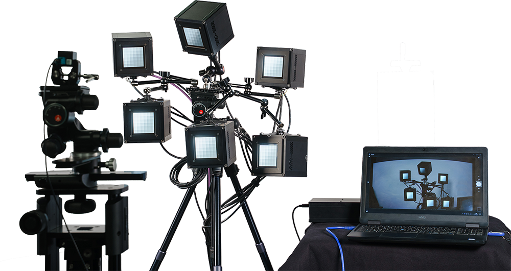
Versatile Light System (VLS)
The Versatile Light System (VLS) offers a solution for multiple machine vision measurements, including high dynamic range measurements. The solution consists of Vega light sources that use DC technology to create a high-stability light source with flicker-generation capabilities. With the VLS, you can test cameras with very short exposure times for high dynamic range and flicker response, which are crucial to understanding machine vision performance (particularly in automotive-grade cameras).
The VLS is optimized for machine vision applications related to ADAS, including contrast transfer accuracy (CTA), modulated light mitigation probability (MMP), and contrast signal-to-noise ratio (CSNR). These KPIs are outlined in the IEEE-P2020 automotive image quality performance standard. In addition, the VLS can perform both spatial and temporal recording measurements as described in the standard.
Test Chart Illumination
As previously discussed, test charts can evaluate most of the crucial image quality factors. It is essential to ensure proper illumination when using test charts, particularly when analyzing the spectrum from low to bright light. A spectrally tunable light source that can generate custom spectra is the most efficient option for test labs. Our iQ-LED light sources use iQ-LED technology to create the custom spectra you need to meet the desired testing requirements.
For reflective test charts (e.g., slanted edges), we recommend the iQ-Flatlights. For transparent test charts (e.g., grayscale targets), we recommend using a uniform lightbox such as the LE7. The LE7 also has near-infrared (NIR) testing capabilities. We even offer integrating spheres such as the CAL1 and CAL2 for production line integration so you can improve the efficiency of your camera calibration on a production line.
Finally, many of our test charts are compatible with the iQ-Analyzer-X evaluation software. This software is one of the market's most advanced and uses AI detection to detect the chart under test and assess the results quickly. We offer a free software version so that you can get started today with your evaluations.
Conclusion
As machine vision technology evolves, so do the demands on image quality testing. Autonomous driving and advanced robotics are just a few areas that will continue progressing and require test methods to adapt. Understanding the challenges of machine vision camera testing and ensuring high image quality performance will remain a cornerstone of technological success.
By combining traditional tests using test targets with more advanced solutions such as the AEON Camera Calibrator, manufacturers can certify that their cameras consistently meet the stringent demands of modern applications and ensure that high efficiency, high performance, and human safety continue to be at the forefront of innovation.