Introduction
Lens distortion is a part of most imaging systems, built-in when the lens is in development. In some cases, lens distortion is simply an aesthetic issue affecting how the image looks to a human observer. However, in the case of computer vision applications, which have experienced remarkable growth in the last decade, lens distortion impacts the ability of the camera to accurately detect the position and size of objects in the image plane.
For example, without the removal of lens distortion:
- Automotive camera systems cannot pinpoint the exact location of other cars, pedestrians, or objects in their field of view.
- Robotic vision systems struggle to grasp objects and maneuver in 3D space.
- Augmented reality headsets cannot accurately project their images for user interaction.
In specific applications such as advanced driver assistance systems (ADAS), driver/occupant monitoring systems (DMS/OMS), augmented/virtual reality (AR/VR), robotics, aerial imaging, cell phone camera object measurement, and space exploration, lens distortion interferes with the camera vision system. As a result, lens distortion must be measured and removed to ensure these applications have a clear vision of what they are seeing so that they or the human operator can make proper adjustments.
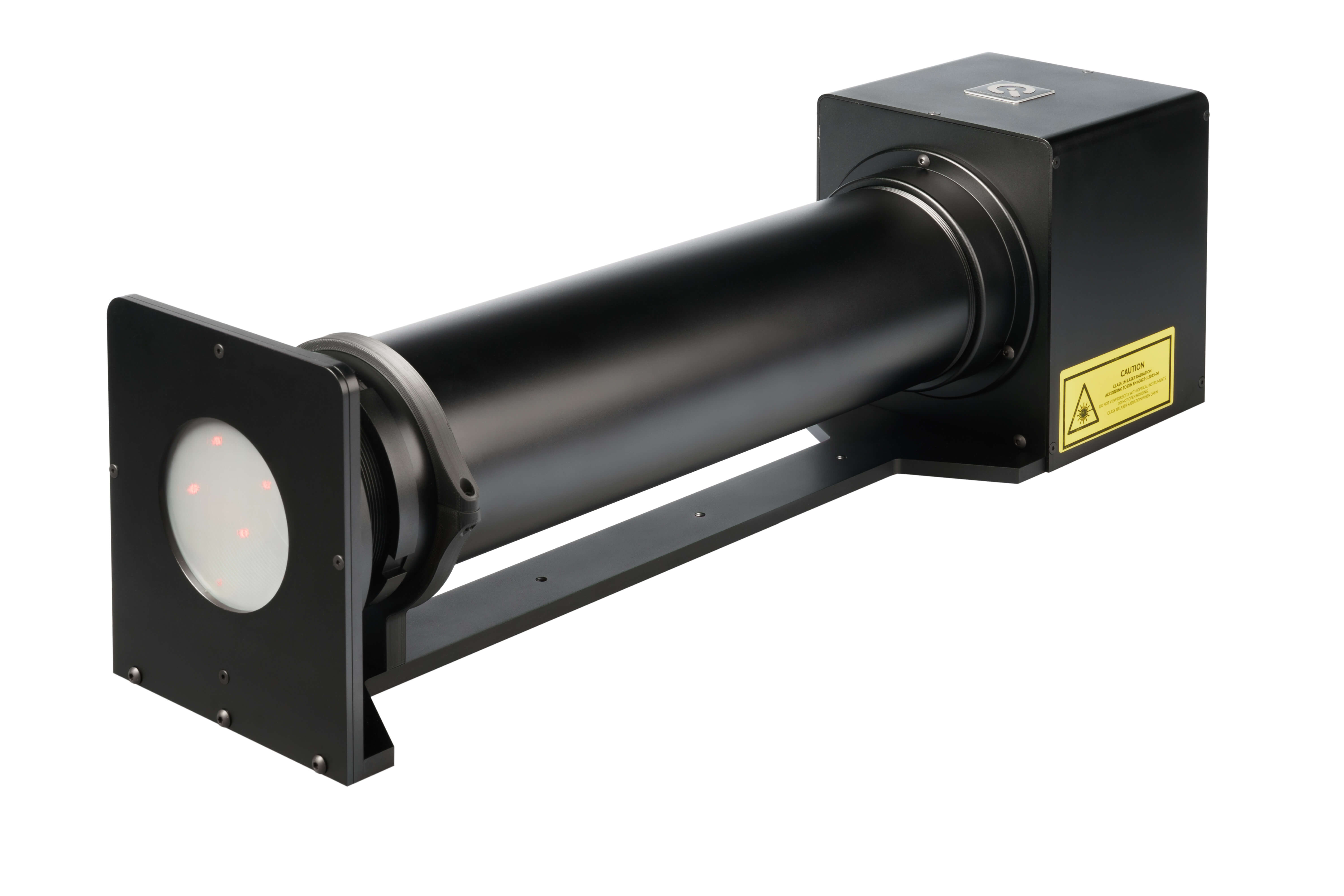
At Image Engineering, we have developed GEOCAL, one of the most advanced testing devices for measuring and evaluating lens distortion. Combining the GEOCAL measurements with open-source software such as OpenCV will allow you to remove the distortion from the captured images of these applications.
GEOCAL introduces a compact solution that maps distortion using a beam-expanded laser combined with a diffractive optical element (DOE). This solution eliminates the need for ample floor space, external light sources, relay lenses, etc., while still providing the ability to measure all lens distortion's intrinsic and extrinsic parameters.
GEOCAL vs. Traditional methods
Traditionally, lens distortion is measured using checkerboard test carts. Using this method, the device under test (DUT) captures images of the chart, and then the lens distortion parameters are extracted. While this method is still valid, in practice, it has many disadvantages, including:
- Setting up a checkerboard test chart system requires a lot of floor space, especially as the camera’s field of view increases.
- Checkerboard test charts require external lighting to illuminate the charts.
- Checkerboard test setups must be reconfigured when calibrating cameras with different FoVs and thus requiring changes to the floorspace, lighting, test charts, and the distance to DUT.
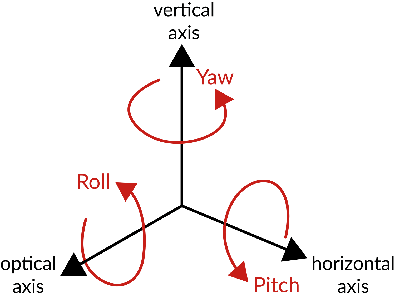
- Checkerboard charts do not measure pitch, yaw, and roll.
- Checkerboard test charts require relay lenses to measure at infinity, especially cameras with long focal distances, and these lenses introduce additional distortion that needs to be eliminated from the measurement.
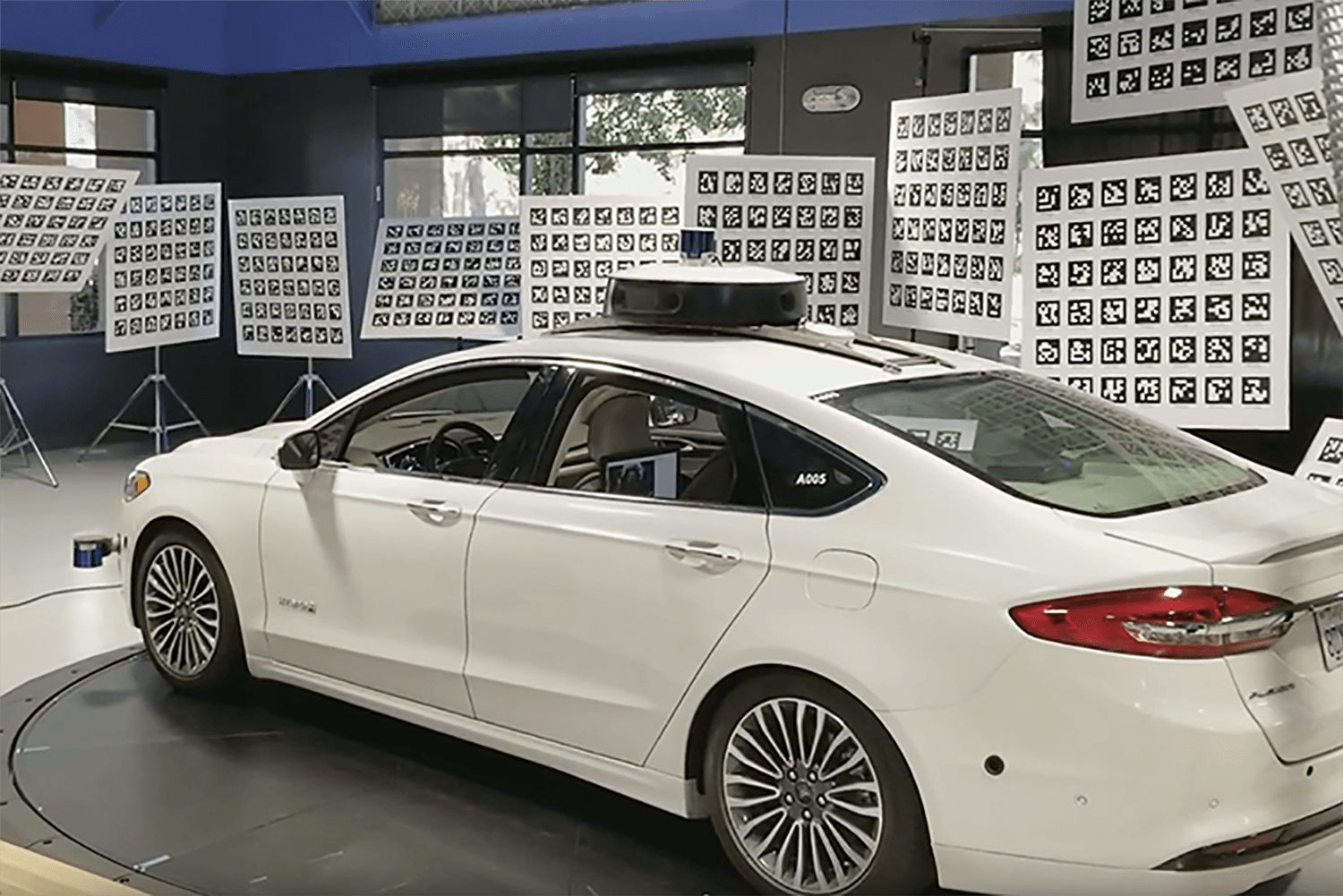
*https://medium.com/wovenplanetlevel5/high-fidelity-sensor-calibration-for-autonomous-vehicles-6af06eba4c26
GEOCAL measurements
The GEOCAL creates a dense point grid originating from infinity, which the DUT then captures. As the geometry of the projected point grid is known, the lens distortion in the captured grid image can be analyzed using specially designed GEOCAL software.
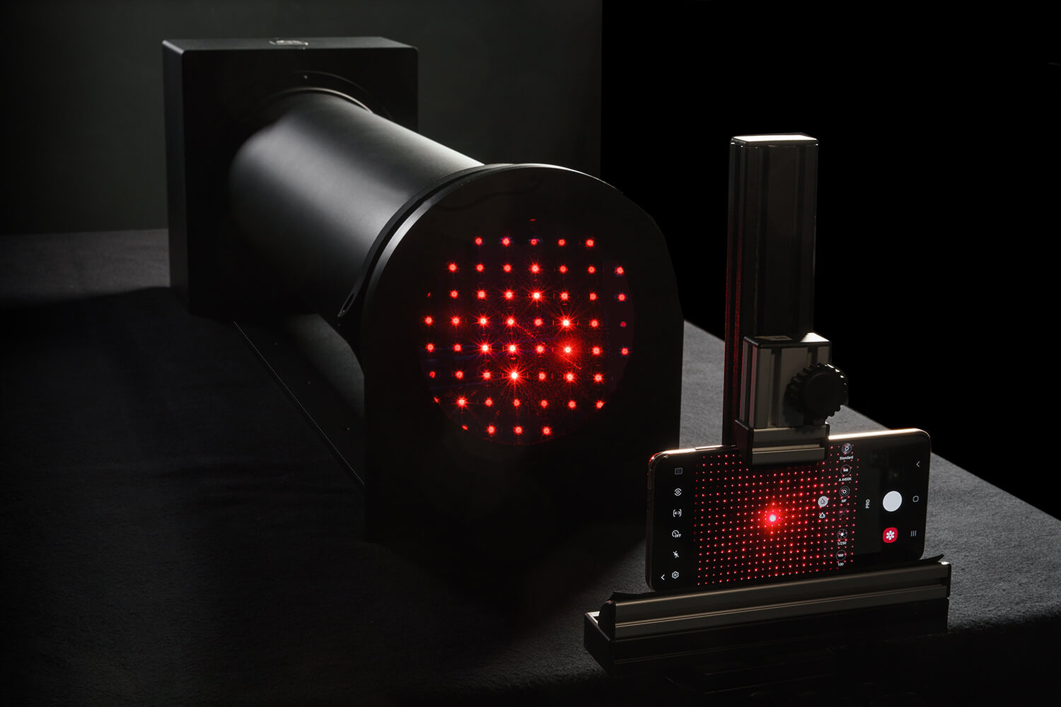
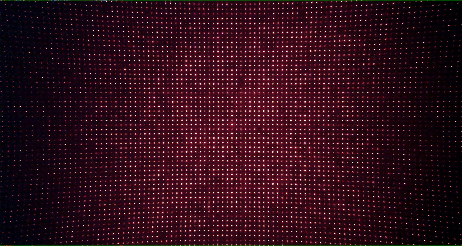
Using the software, you can determine the intrinsic parameters (radial and tangential distortion coefficients, principal point, focal length) crucial for distortion removal. In addition, extrinsic parameters (pitch, yaw, and roll) can also be measured for stereo camera pair alignment or to calibrate a camera’s angular orientation.
Typically, we recommend using OpenCV when removing distortion. If using OpenCV, a compatible lens model is crucial to derive the intrinsic and extrinsic coefficients from the grid image. The calculated parameters can be output as either CSV or XML files. The user can also configure some lens model coefficients for radial distortion.
Below is an example of XML output from GEOCAL (see download section at the end of this article to download the example results).

Distortion removal with OpenCV
The code will interpret the camera calibration parameters from the CSV file output and apply them to an image using the OpenCV “undistort” function (see download section at the end of this article to download the example results).
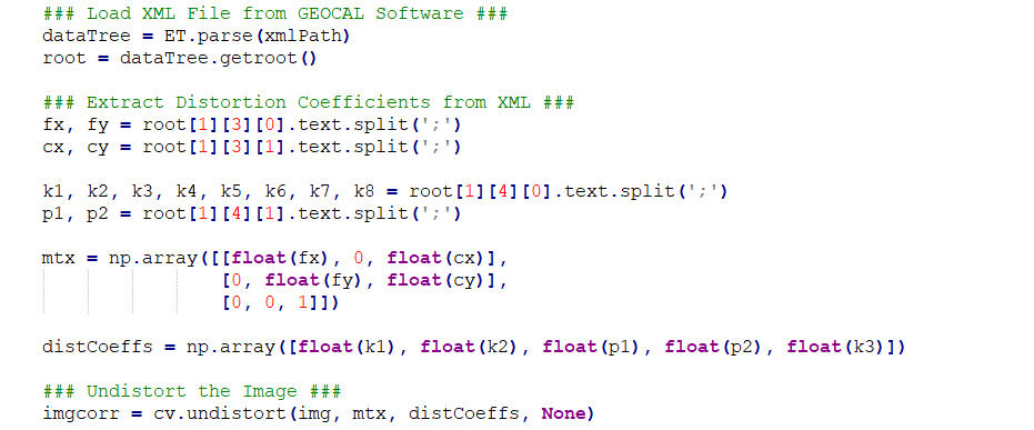
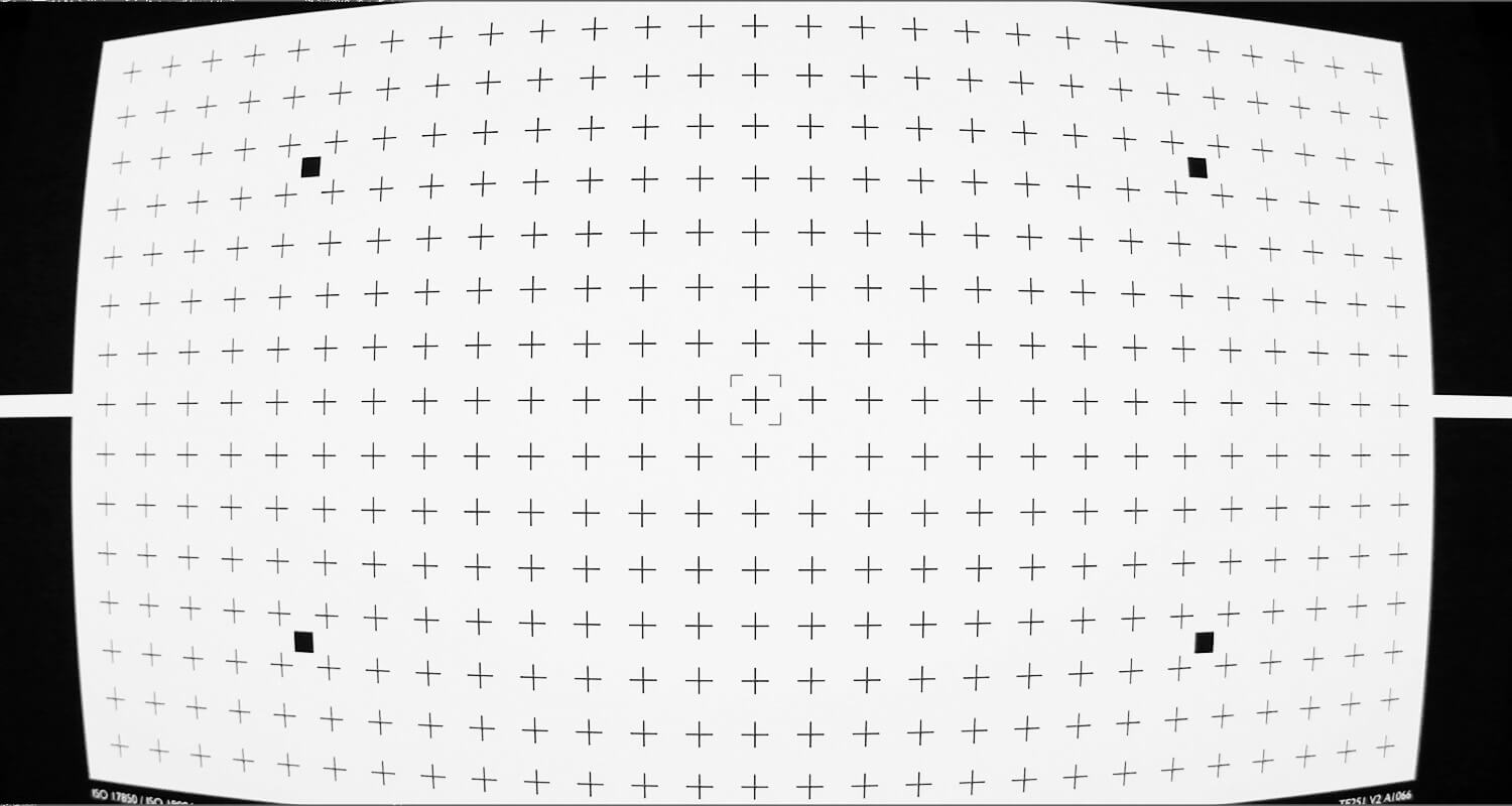
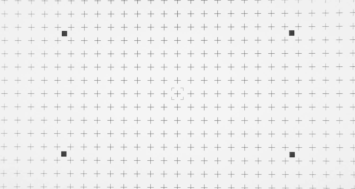
Using OpenCV, lens distortion can be removed from the original image, and the camera can be geometrically calibrated.
Files
Test images, python script and Geocal xml file:
Distortion_Removal_Example.zip
OpenCV resources
Getting started with OpenCV:
https://docs.opencv.org/3.4/d9/d5a/classcv_1_1sfm_1_1libmv__CameraIntrinsicsOptions.html
Distortion removal:
https://docs.opencv.org/3.4/da/d54/group__imgproc__transform.html

