Time-of-Flight Characterization
TechnologyIntroduction
Time-of-flight (ToF) camera technology refers to the ability of the camera and sensor system to accurately determine object distances in the field-of-view (FoV) and 3D map the scene. This technology is helpful for various applications, including augmented and virtual reality and advanced driver assistance systems (ADAS). ADAS applications, in particular, use ToF technology to assist them in understanding and reacting to their surroundings in real time.
How does ToF camera technology work?
ToF camera technology emits short bursts of infrared light and measures the exact time it takes for the light to travel to the object in the scene and then bounce back to the camera sensor. The ToF camera system will then use this time interval to calculate the distance to the object.
This measurement process is repeated numerous times per second and thus allowing the camera to capture a series of depth measurements to create a 3D map of the environment. This technology makes it ideal for camera and sensor systems in autonomous vehicles.
ToF technology and ADAS applications
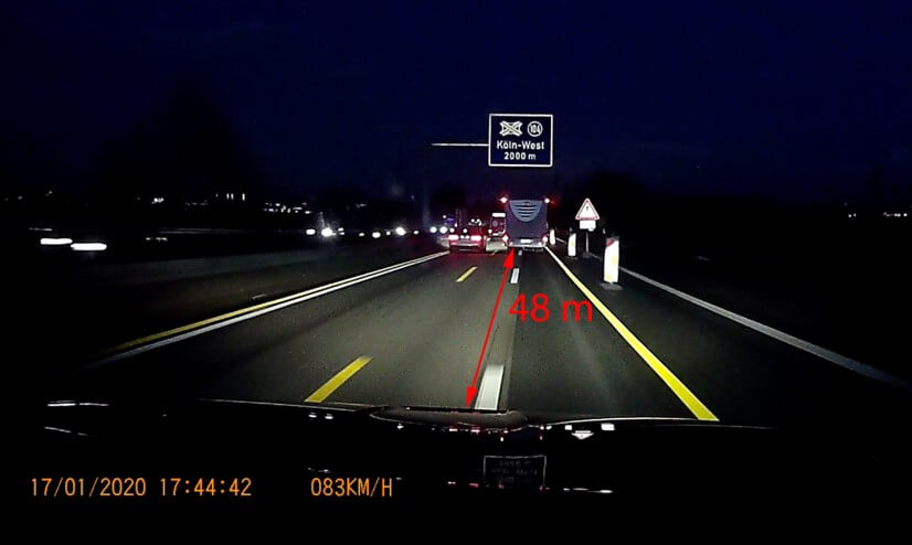
ToF technology is utilized in most ADAS driving applications to help them accurately interpret their surrounding environment. ToF cameras capture depth information, allowing the vehicle to detect and locate objects in real time. Once objects are detected, the ToF system can 3D map the scene to enhance these systems' perception and decision-making capabilities (e.g., accelerating or braking, depending on the situation).
ToF camera technology can also be integrated with other sensor technology, such as LIDAR and RADAR, to provide a more comprehensive overview of the environment. Together these systems allow the ADAS application to accurately detect and locate objects, such as other vehicles, pedestrians, traffic lights, etc.
Without these systems, it would be difficult for autonomous vehicles to function safely in complex environments. However, due to the nature in which these systems operate and the risk to human life, they should not be implemented into ADAS applications until they are calibrated and rigorously tested to ensure the highest level of performance and safety.
Calibrating and characterizing ToF cameras
ToF camera systems should be calibrated and characterized before use to ensure high performance and safety. Similar to traditional camera testing, ToF cameras must be calibrated and tested for various image quality factors.
Geometric Calibration
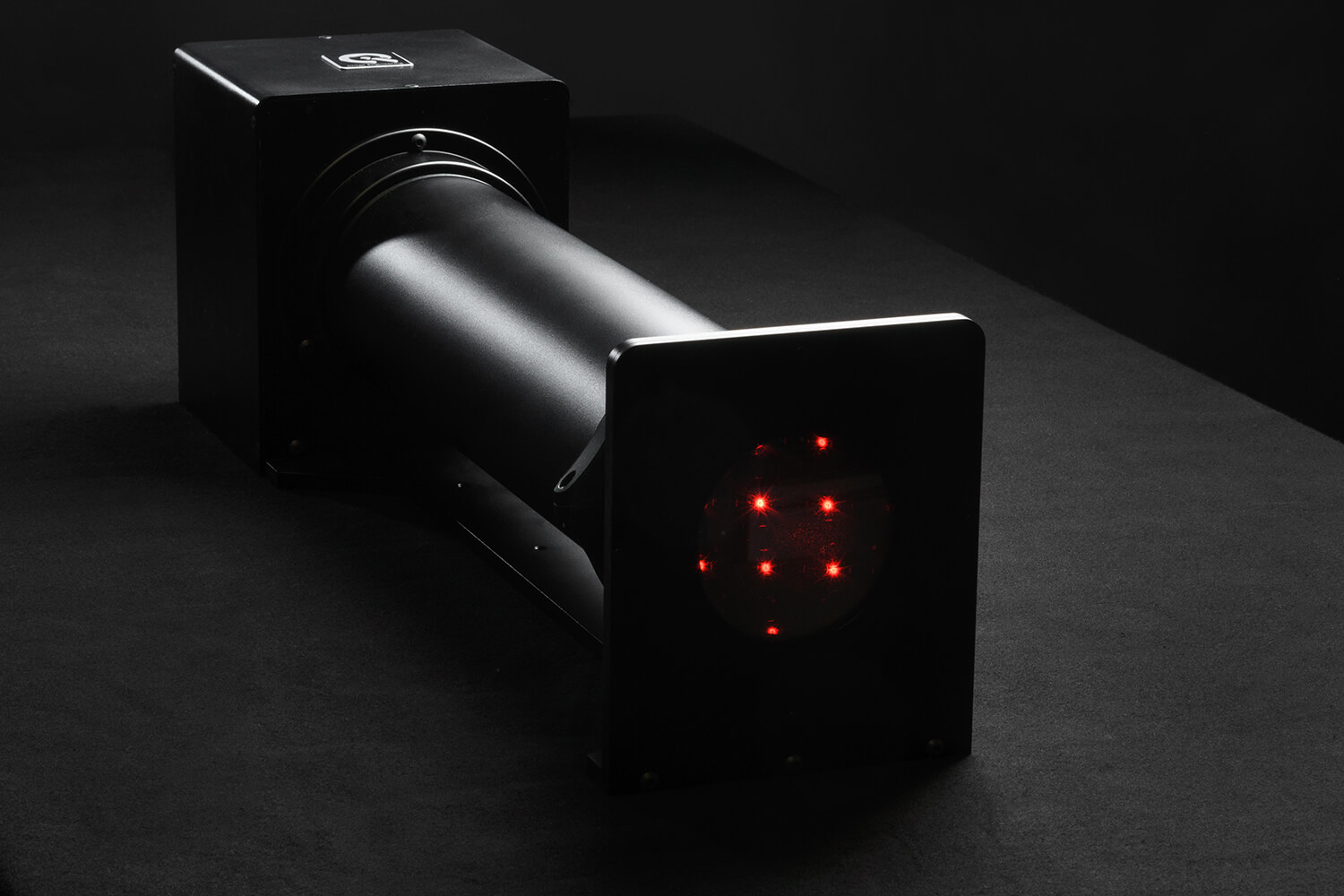
Geometric calibration is vital for ToF systems that rely on detecting and accurately 3D mapping objects in a moving scene. After proper geometric calibration, the camera system will more precisely measure distances and identify objects in a scene. The system will also better adjust for high distortion levels and accurately align stereo camera pairs. In automotive applications, distances to objects are calculated based on the measured geometrical characteristics of the camera or a stereo camera pair. In our experience, geometric camera calibration is best done with the compact GEOCAL device, which generates a grid of light spots from infinity. Learn more about geometric calibration here.
SFR and resolution characterization
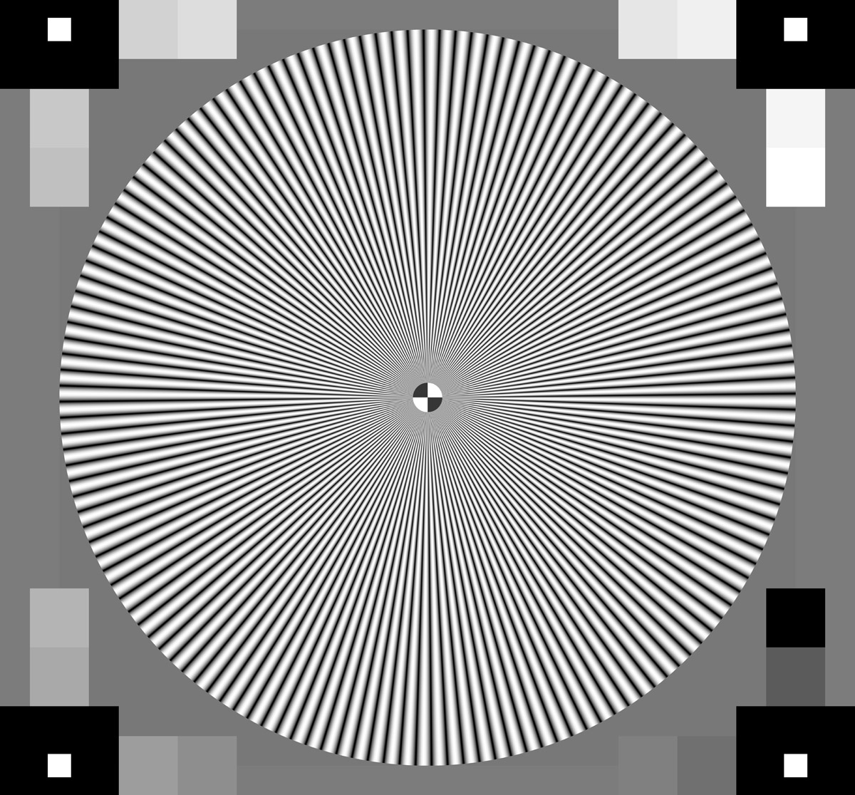
Another crucial ToF camera element is testing the spatial frequency response (SFR) to determine resolution performance. SFR describes how well the system under test can reproduce a range of spatial frequencies on a scale from 0% (complete loss of information) to 100% (perfect reproduction without data loss). If the ToF system is experiencing a lower percentage, then the camera will struggle to correctly detect objects in the scene, especially in low-light or extremely bright-light scenarios. The SFR can be determined by using a slanted edge target (e-SFR) or a sinusoidal Siemens star target (s-SFR), and test methods are outlined in ISO 12233.
Signal-to-noise ratio (SNR)
Noise refers to artifacts in an image that do not originate from the original scene content. A ToF camera system will encounter trouble identifying different objects in the scene if there is a high noise level. This problem is particularly dangerous for ADAS applications that must correctly identify an object to determine the correct adjustment. Thus, obtaining the SNR value of a camera is crucial for ToF systems.
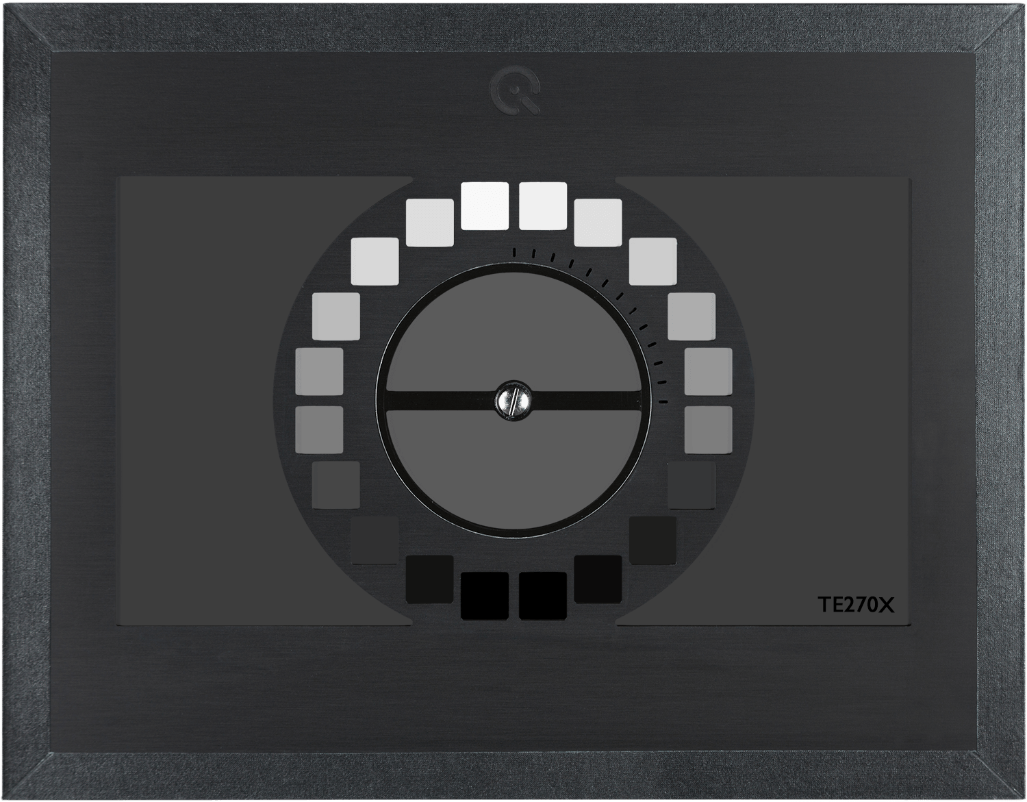
The recommended test method to obtain the SNR uses an OECF test target based on ISO 14524 (e.g., TE270X). These test targets use a range of grey patches where the SNR is calculated for every patch to provide a function of SNR vs. Luminance to determine the amount of noise in an image.
Light reflection (flare) characterization
Flare is unwanted light in an image that did not originate from the related scene object. In an automotive scene, flare often appears as reflections (from windshields, headlights, etc.), which can significantly affect object detection or identification by a ToF camera. Measuring the impact of flare on a camera sensor is traditionally done following the methods of ISO 18844 and using a test chart. However, for ToF cameras, flare is better characterized using test targets that can reflect light to the sensor. These test targets will help ensure proper ToF camera system depth calibration.
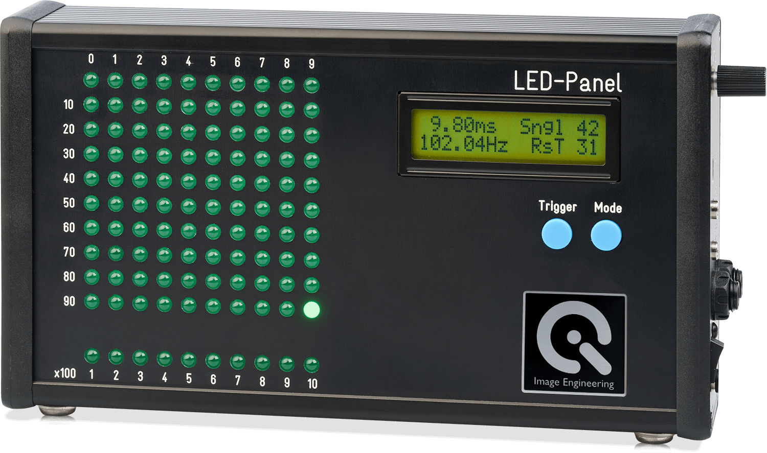
Timing measurements
Depth mapping a scene requires precise timing measurements to determine the distance of objects in a scene. ToF camera systems release a signal burst and measure the exact time it takes for the signal to reach the object and bounce back to the sensor, thus determining the distance. For proper timing calibration, we recommend following the methods in ISO 15781 and using a timing measurement device such as the LED-Panel.
System validation with the ground truth
Once fully calibrated and characterized, the ToF system can be validated by comparing the measurements to the ground truth. The ground truth of a 3D depth measurement can be determined by physical measurements or by using advanced solutions in a test lab, such as a homogeneously reflecting target.
Building a ToF testing solution in a test lab
Many factors indicated in the section above can be measured using 2D test charts. However, for a ToF camera system, 2D test targets are impractical as the goal is to 3D map a dynamic scene. At Image Engineering, we use the principles of ToF technology to develop advanced test targets and test stands for ToF camera testing and depth calibration in a controlled test lab environment.
Once calibration is completed, any remaining errors are more easily identifiable by comparing the ground truth to the calibrated depth information. Repeating this process from several positions will clearly show the ToF camera's depth mapping performance and where data calibration and processing must be improved.
If you are interested in developing a ToF testing solution based on your requirements, please contact our sales team. They will offer advise on possible solutions based on your specifications.
Want to learn more about how to build a ToF technology?
Contact us to set up an introduction with our engineers.