Introduction
One of the most crucial components of a camera system is the performance of its various timing parameters. These parameters are essential to capturing and processing images and help control a camera system's exposure, synchronization, and overall performance. During the development stage of a camera system, developers must understand and test these timing metrics using the proper test equipment to ensure the system is functioning correctly and can produce images with a high level of image quality.


Timing parameters
Understanding and controlling timing parameters allows camera system operators to achieve their desired exposure settings, motion capture, and overall image quality. Each parameter plays a crucial role in the performance and capabilities of a camera system in different scenarios.
Shutter speed and Exposure time
Shutter speed in traditional cameras refers to the duration the system's shutter remains open. For a camera system without mechanical shutter, e.g., mobile phones, we use the term exposure time to indicate when the camera's image sensor is "open" and exposed to the light.
Faster shutter speeds or exposure times can reduce motion blur. In comparison, lower speeds or longer exposure times allow more light to enter the camera, which is essential when capturing low-light scenes, but if left open too long, it can result in a blurring effect. Shutter speed is generally measured in fractions of a second, such as 1/250 or 1/50.
Autofocus time
Autofocus time determines how quickly and accurately the camera system can focus on the subject in the scene. A fast and precise autofocus performance allows users to capture sharp images in various shooting conditions, including fast-paced situations with moving subjects. It is crucial to test autofocus under different illumination conditions, especially in low light, where the camera may struggle to identify and focus on the subject.
Shutter and Shooting time lag
Shutter time lag refers to the time between initiating the camera's trigger and the actual start of the image capture. This parameter is significant whenever precise timing is required, e.g., capturing fast-moving objects as they appear in the frame.
Shooting time lag is the same as shutter time lag but includes autofocus time. In other words, we are measuring the time interval between pressing the camera's trigger and the autofocus time before the actual start of the image capture. Shutter and shooting time lag should be evaluated for their performance to ensure all user requirements are possible.
Frame rate
Frame rate describes the number of individual frames captured and stored per second by the camera. Higher frame rates better stabilize motion in a scene and are, therefore, more beneficial for video recording or fast-paced scenes. Frame rate is measured in the number of frames captured per second (fps). Standard frame rates include 24 fps (cinema production) and 30 or 60 fps (home video recording). Evaluating frame rate performance requires the correct shutter speed to capture the desired number of frames.
Display refresh rate
Camera display refresh rate refers to the number of times the image on the camera's display is refreshed per second. A higher frame rate will make a series of images appear smoother during the transition from image to image. A lower refresh rate often leads to problems with object alignment based on the information on the display. Display refresh rate is measured in Hertz (Hz), which indicates the number of refresh cycles per second.
Rolling shutter speed
Rolling shutter describes a certain way that a sensor is read out. While cameras with a mechanical shutter can read out even when there is no light on the pixel, a camera with a rolling shutter and not mechanical or global (i.e., a camera that captures the whole frame in one instant) will read out line by line. Depending on the difference between the first and last line read out, the objects moving in this time will show a distortion.
Startup time
Startup time refers to the time it takes for the camera to reach full working capability after pressing the power button. While this may not seem like a crucial timing parameter, it can be essential to consumers. For example, if a consumer is using a camera that is currently off or stored away, how fast can it be ready to take a picture once they turn it on and activate it? If the camera needs more than five seconds, then it is likely that the person will miss the moment they want to capture, especially if it is a moving object.
Testing the timing parameters
Each timing parameter should be thoroughly tested during development to ensure a high-performing camera system. At Image Engineering, we have developed the LED-Panel to do just that. This device is in its fifth generation and has become one of the market's most popular timing measurement devices due to its flexibility and reliability.
LED-Panel (V5)
The LED-Panel is a compact device with a 10 x 10 LED lightboard that provides various illumination modes and frequencies depending on the measured parameters. All the timing parameters mentioned above can be measured using this device, and many can be measured in one image. The latest version (V5) offers the ability to dim the LED board to improve low-light testing, and we have also improved the accuracy under bright light conditions. A version available for near-infrared (NIR) testing is made of LEDs in the IR range.
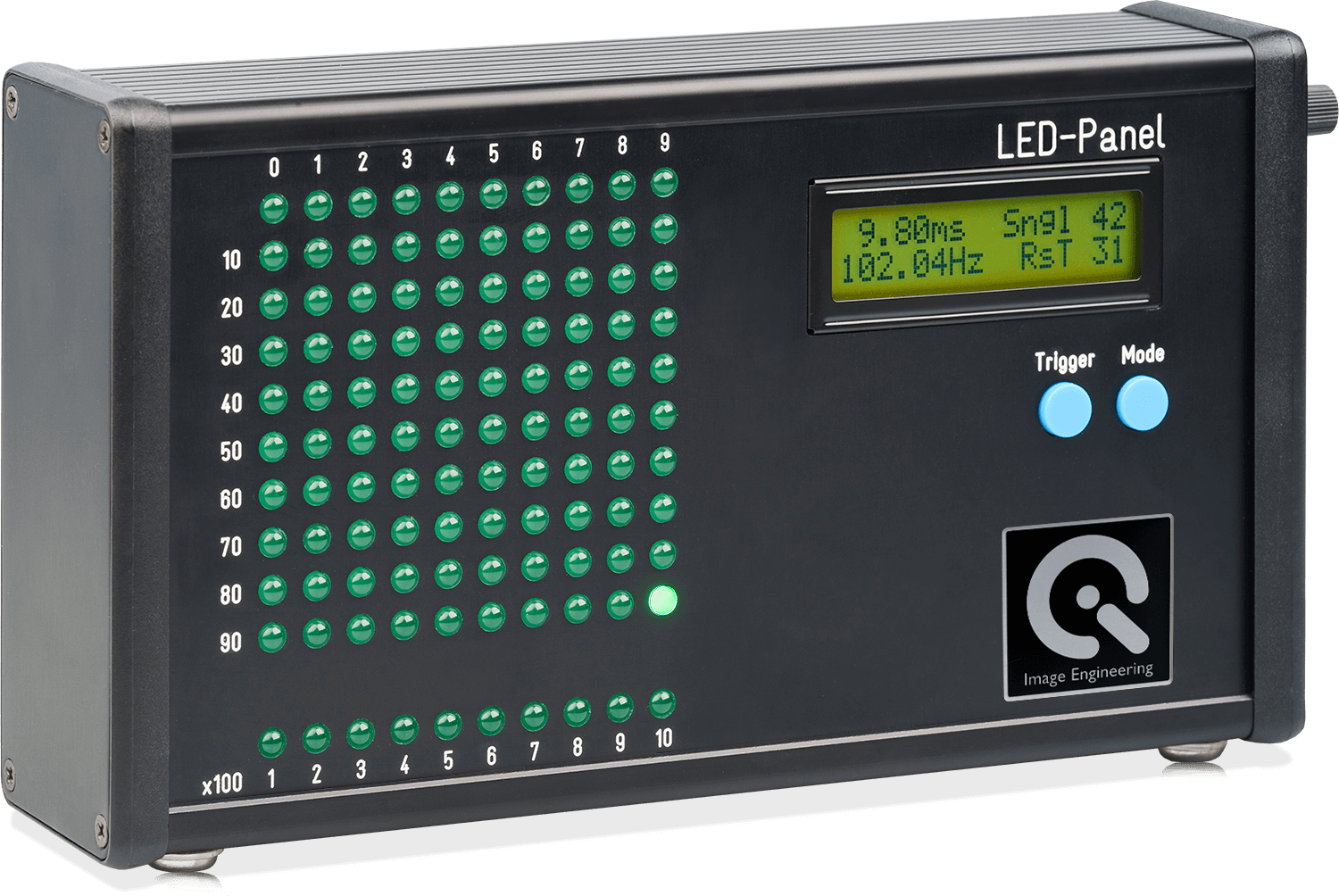
Our engineers have developed the LED-Panel to meet all the requirements of ISO 15781, which describes measurement methods and performance thresholds for various timing metrics, including shooting time lag, shutter (and negative) shutter release time lag, frame rate, startup time, etc. The LED-Panel is also featured prominently in the VCX standard for testing the timing parameters of mobile phones and webcams.
LED-Panel control software
The LED-Panel can be controlled directly on the device itself, but it is also equipped with uniquely designed control software with a USB interface and a command line interface. In addition, the software acts as the primary control software for the iQ-Trigger. This device is often used with the LED-Panel as it provides an option to automatically press the shutter release button while eliminating human error and controlling accuracy.
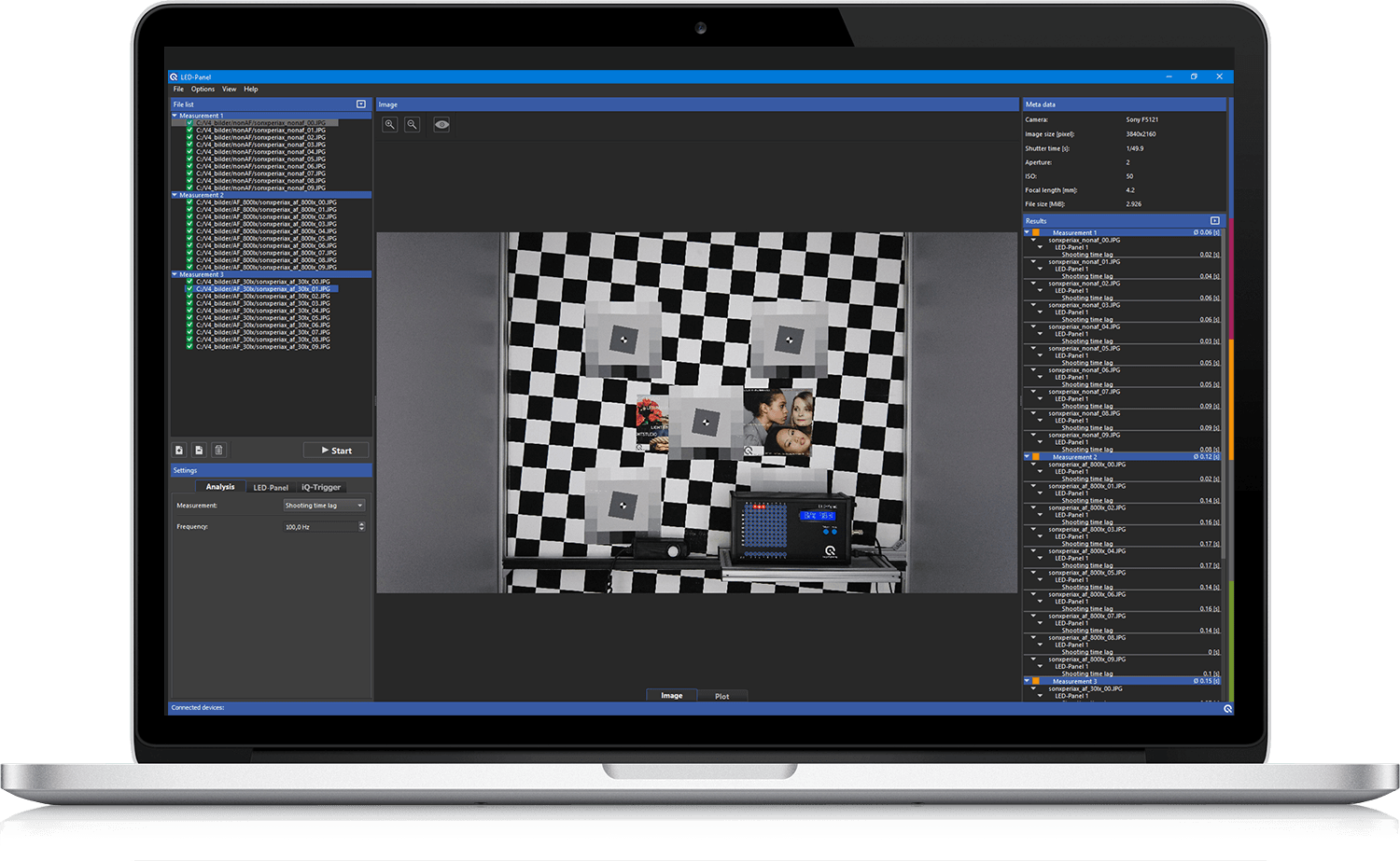
The control software allows users to create test sequences and analyze the captured test images. In addition, we offer an LED-Panel C++ API for easy integration with other products (e.g., iQ-Trigger). Modifying the start and stop timing of the device and changing the measurement modes are also possible with the API.
Timing Solutions
Due to its compact design (240 x 130 x 55 mm and weighing one kg), the LED-Panel can be easily incorporated into any image quality test lab and combined with various other products to create advanced timing solutions.
TE42-LL Timing test chart
One of our more popular timing solutions is the TE42-LL Timing multipurpose test chart. This test chart directly incorporates two LED-Panels into the chart for a complete image quality test. With this chart, you can measure image quality factors such as resolution, texture loss, color accuracy, dynamic range, and the critical timing parameters in one test image. This chart is also designed to be used in low-light test scenarios.
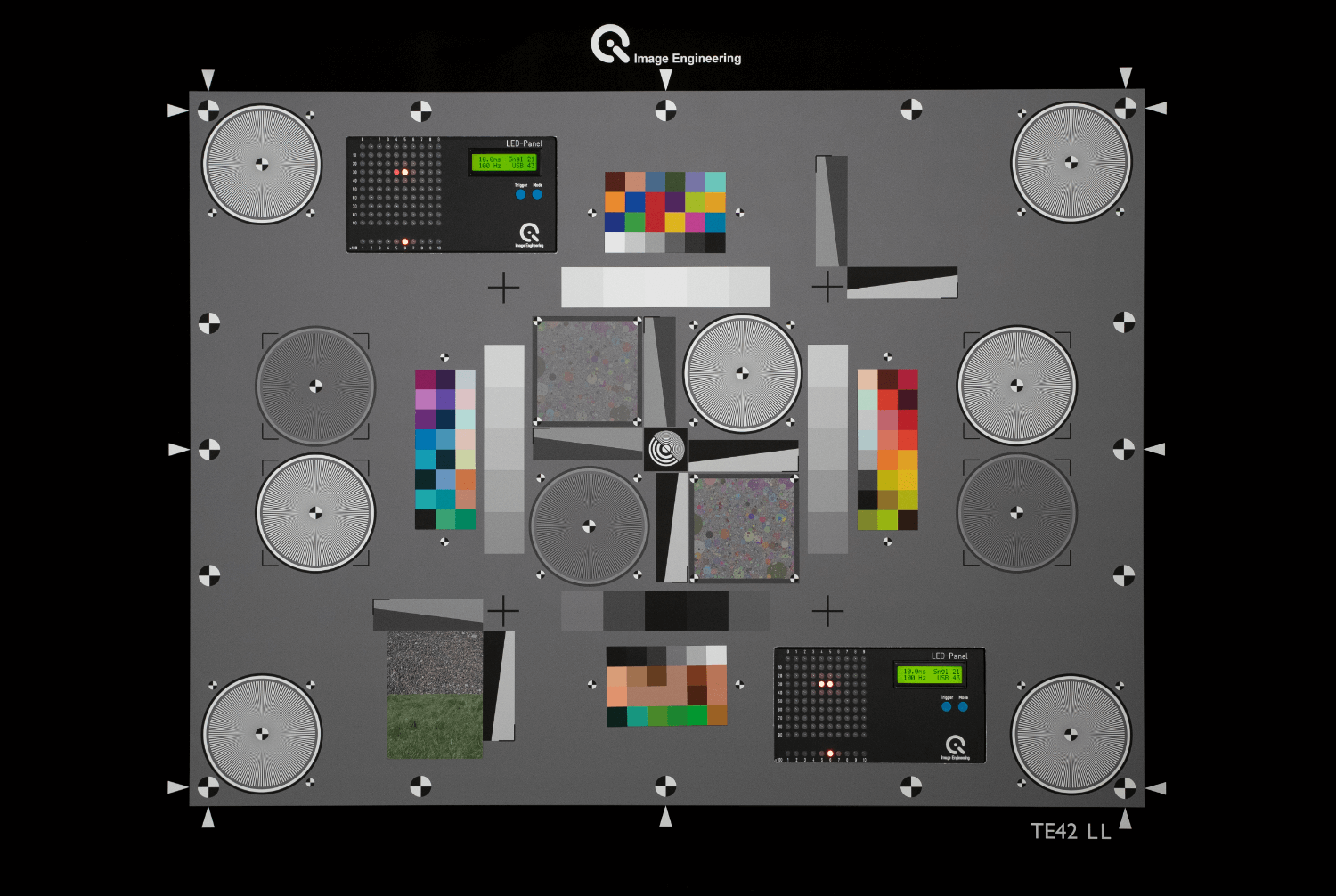
As you can see in the image above, we use two LED-Panels in the chart to ensure that we can more accurately analyze the effects of rolling shutter speed. This chart is referenced directly in the VCX-PhoneCam standard.
iQ-Near Focus
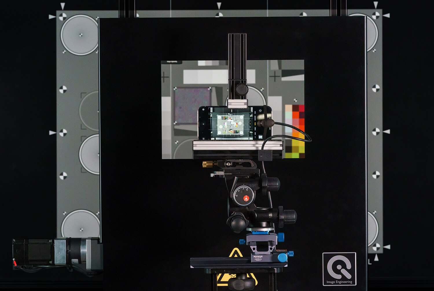
Combining the LED-Panel with the iQ-Near Focus provides another powerful solution for timing measurements. The iQ-Near Focus is designed to evaluate a camera's autofocus performance, and it uses a motorized translucent checkerboard test chart to focus the camera at a near distance precisely. When you press the remote release, a motor quickly lowers the checkerboard test chart out of the optical path, and the camera will focus on the test scene behind. In this case, an LED-Panel can be positioned in the background (or a TE42-LL Timing chart) to simultaneously measure the camera's timing and autofocus performance.
lightSTUDIO
In addition to the solutions above, the LED-Panel can be incorporated into other devices such as the lightSTUDIO. Here you can analyze a camera's response to natural objects (as opposed to test charts) while also testing the timing parameters with the integrated LED-Panel.
VIDEO
All told the LED-Panel is one of the most reliable and flexible camera timing measurement devices available on the market. With just one device, you can measure all the crucial timing parameters of camera systems. It can also be easily integrated into almost any test lab setup and combined with other timing measurement devices to create solutions that fit your testing requirements.
Contact us
Contact us at for more information on timing measurement solutions.

