Generally, the function of rotationally symmetric optical systems is to form an image that is geometrically similar to the object, except for some particular systems, such as fish-eye lenses and eyepieces, where this condition is deliberately not maintained. Ideally, this function is accomplished according to the geometry of perspective projection. Departures from the ideal image geometry are called distortion.
ISO 9039 is the standard that defines methods to measure a lens that is separated from a camera. Sometimes the lens cannot be removed from a camera or the apparatus and time-consuming method described in ISO 9039 is not available. Therefore this standard was developed and defines methods to measure distortion using a camera lens combination.
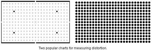
One method that uses the camera lens combination is the so-called picture height distortion also often referred to as TV Distortion. This method requires a test chart with a regular grid of geometric structures like the ones shown below.

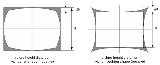
This method is based on a system that shows a steadily increasing distortion from the image center to the corners. It quantifies the bending of a straight line in the image of the original at the top edge of the image (see figures below). The ratio of the bending over the height of the image times 100 is the picture height distortion in percent. This method is compliant with the one described in EBU Tech3249.
 with ΔH > 0 for pincushion and ΔH < 0 for barrel distortion

Lens Geometric Distortion

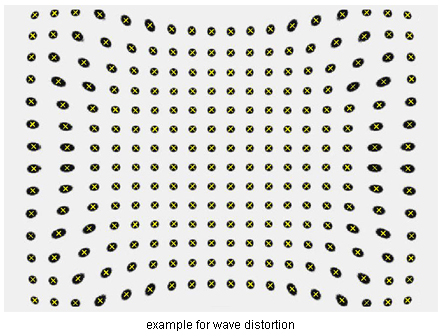
Some systems especially small ones in mobile devices are corrected for distortion at the maximum image height. These systems show the highest level of distortion at lower distances from the optical center. The resulting type of distortion is a mixture of barrel and pincushion distortion and described with the term wave distortion.
For systems with a wave distortion the measured picture height distortion can be zero or close to zero although a strong distortion is visible in the image. To measure the distortion for these systems the lens geometric distortion is used.
It is assumed that the distortion close to the optical center is zero therefore a regular grid is calculated based on the geometric positions of the 9 structures (3x3) in the center of the image. This grid is expanded on the whole image and defines the nominal positions for each of the structures.
The distortion is then measured using the following formula: where
where
H* is the distance of the dot from the image center
H is the nominal distance of the dot from the image center based on the expanded regular grid
The maximum Distortion measured for any of the geometric structures in the image is the one that is reported.
This method is described in the CPIQ (Cell Phone Image Quality Group) deliveries of phase two which Image Engineering was participating in.
dw

