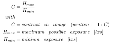
The dynamic range (DR) describes the maximum contrast ratio, which can be captured by a digital camera without highlight clipping and a signal in the dark patches which can be divided from noise. The dynamic range is a primary characteristic value of the image receiving sensor, but is influenced by the used lens in camera system and the image processing.
There are two methods to get the OECF (opto electronic conversion function) of a camera: via "focal plane" or "scene based". Both methods generate the OECF from some different sensor exposures. To calculate the DR, it is necessary to determine the first useful signal and the exposure which leads to clipping.
FOCAL PLANE
To use the focal plane method, the lens of the camera system has to be removed, so that the sensor can directly be exposed by a light source. The intensity of the light source will be increased successively and pictures were taken at several exposures. The OECF can be obtained by plotting the log exposure values versus a mean digital value from the corresponding images.
SCENE BASED
If you cannot remove the lens of the camera system (or do not want to perhaps if you want to have a test of the whole system) you can use the scene based method to get the OECF by using e.g. the TE241 (fig. 1). There are several patches radial symmetric to the image center with calculated densities mentioned in ISO14524. After capturing this test chart, it’s possible to obtain the OECF by plotting the mean digital value of each patch versus the corresponding log luminance. The main difference with this method is, that the lens has an influence on the obtained DR.
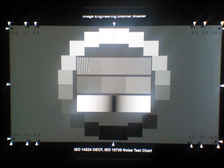 fig 1: TE241 captured by a camera;
notice the outshine of the light
patches – this can lead to a lower DR
The DR can now be calculated with the known OECF. Therefore you have to determine the luminance / exposure at which the SNR (signal to noise ratio) is equal to 1, and the luminance / exposure at which the clipping occurs (ISO 15739). If you get a luminance at SNR threshold of about 4 cd/m² and clipping starts at 1100 cd/m² (see fig. 2), the contrast ratio is

This camera is able to capture a scene with a contrast of 1:275. The DR is calculated in f-stops:

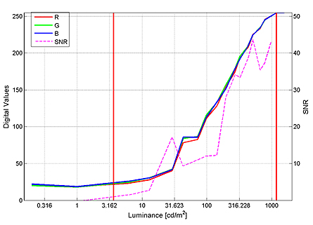
fig. 2: sample OECF (scene based); the left vertical red line indicates the luminance at SNR threshold, the red vertical line shows the luminance at which higher luminance values do not lead to a different signal (clipping)
There could be differences between the DR calculation if you use either the "scene based" or "focal plane" method. The reason for that is the mentioned issue with the existence of stray light through the lens. The contrast ratio will be much lower than without stray light or if you have chosen the "focal plane" method. The amount of stray light will be added to the exposure as follows:
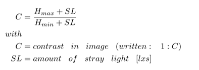
If Hmax would be 1000 [lxs] and Hmin 1 [lxs], the contrast ratio will behave like the function in fig. 3 if stray light increases. The DR would be 9.96 [f-stops] (no stray light). If the stray light would increase the exposure with 1 [lxs] the DR will drop to 8.97 [f-stops].
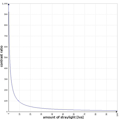
fig. 3: contrast ratio plot against straylight
CONCLUSION
Some image sensors are able to capture a high dynamic range, but if the used lens is not able to transmit the scene contrast, there will be a loss. If it is necessary to get the DR of the sensor only, the focal plane method should be used, but this value is quite abstract, as you need an optical system to capture an image.
ck

